Electronics
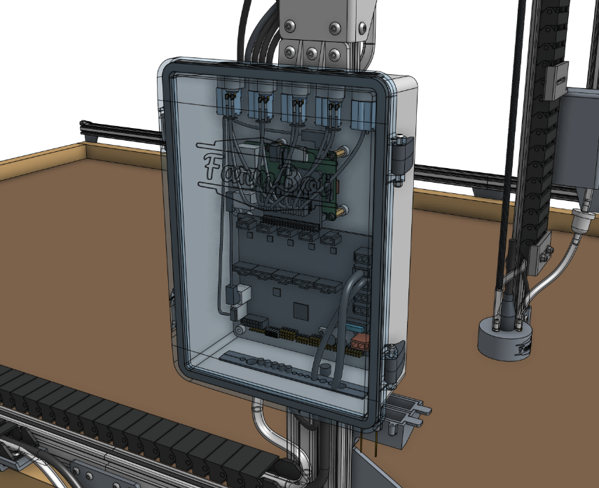
The Agriduino and Raspberry Pi are the central components of the AgriBot from an electronic systems perspective.
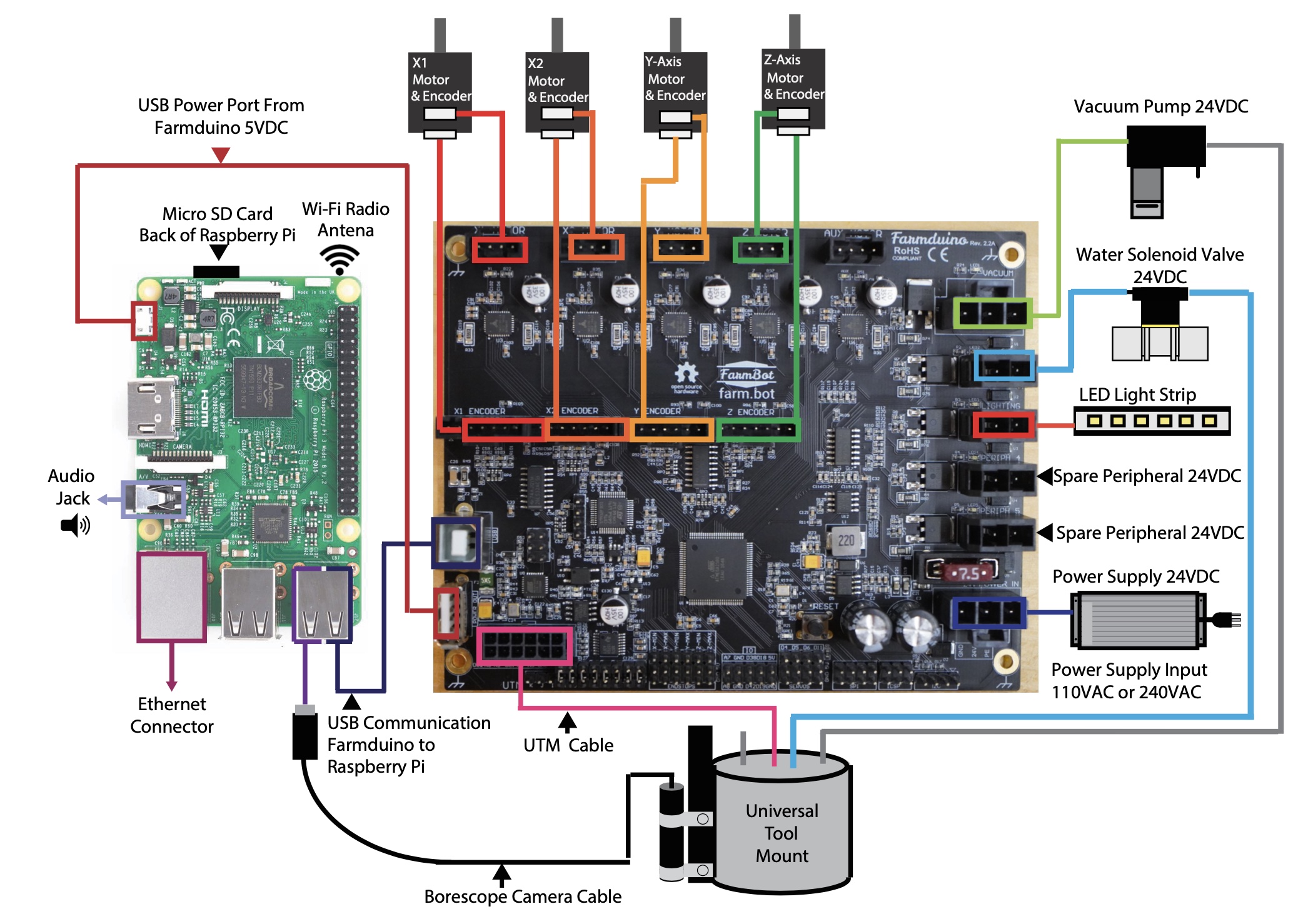
The diagram below shows how the other electronic components connect to these boards, as well as how the two are connected to each other.
The Agriduino microcontroller uses Arduino architecture and it communicates with the Raspberry Pi using a G-code like language.
The Agriduino controls the stepper drivers and motors, as well as the UTM and peripherals.
The Agriduino provides power and control to all the electronic components of the AgriBot.
The board has a layout and connectors that are optimized for AgriBot’s various peripherals and motor requirements.
Meanwhile, the Raspberry Pi is the web-connected brain that keeps track of AgriBot’s plants, sequences, regimens, events, and settings.
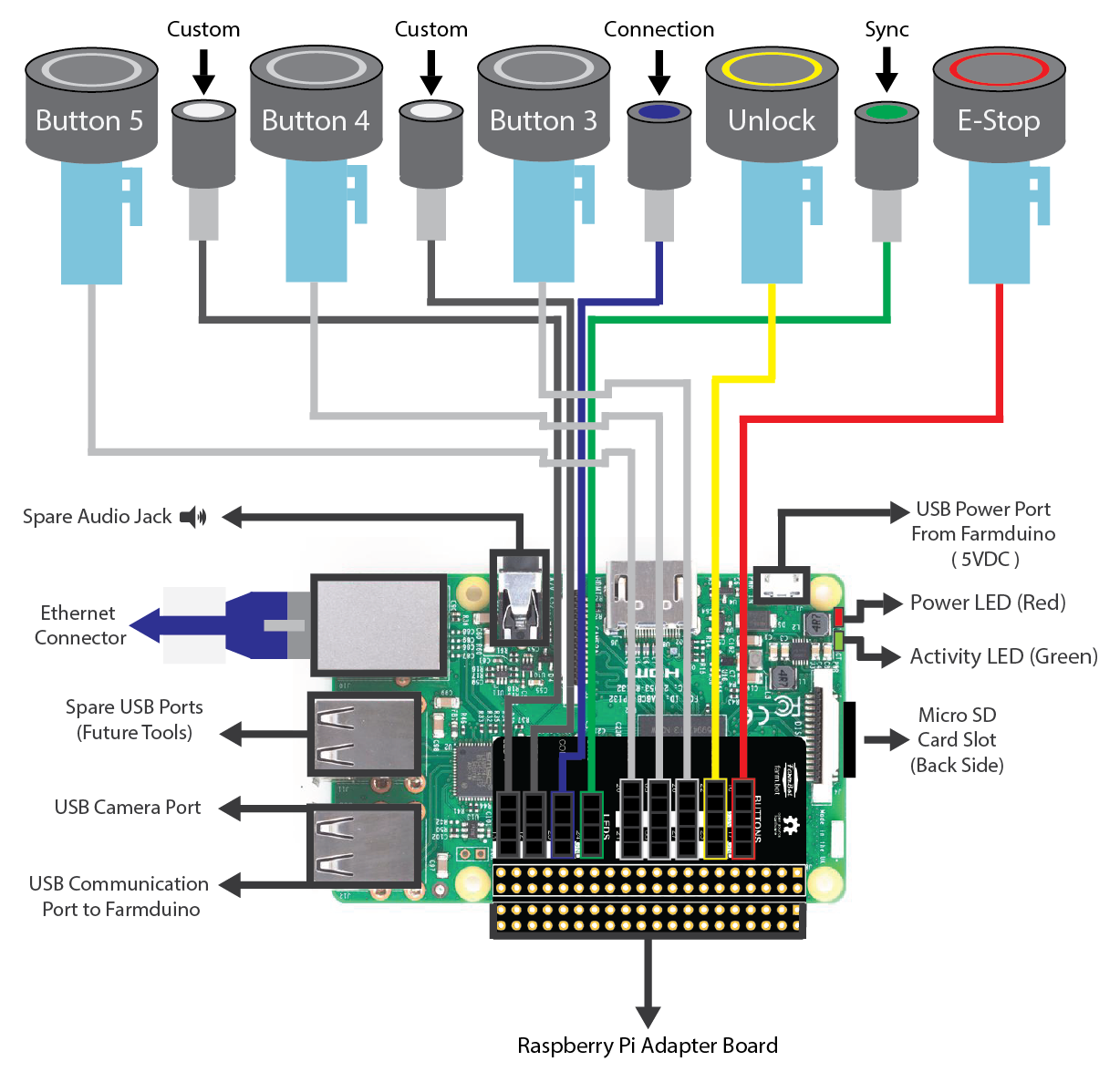
Additionally, the Raspberry Pi is responsible for taking photos with the USB camera, and monitoring and controlling the push buttons and LEDs on top of the electronics box via the Pi adapter board.
Step 1: Attach the electronics box to the gantry
Attach the pre-assembled electronics box to the left gantry column using six M5 x 10mm screws and tee nuts.
The top flange of the box should be butted against the bottom edge of the gantry corner bracket.
Step 2: Connect the peripherals
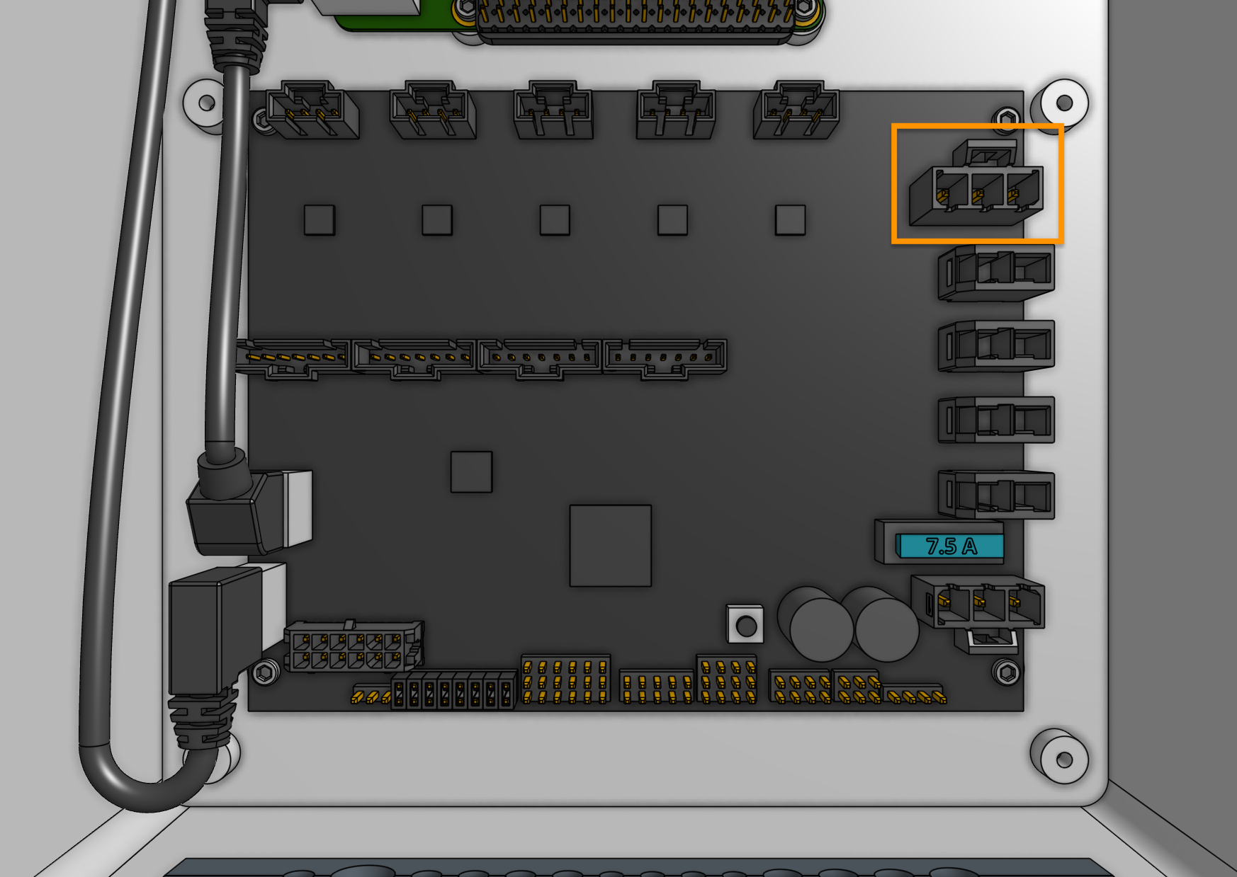
Connect the vacuum pump cable (with gray heat shrink) to the Agriduino peripheral connector labelled VACUUM (the top right connector on Agriduino). The connector will only fit in one direction.
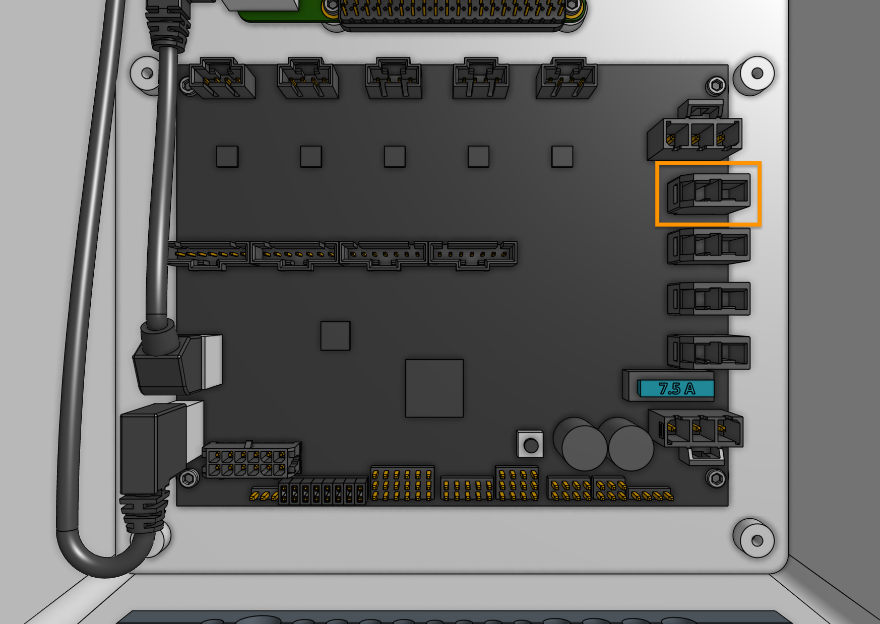
Connect the solenoid valve cable (with blue heat shrink) to the Agriduino peripheral connector labelled WATER (directly underneath the vacuum connector). The connector will only fit in one direction.
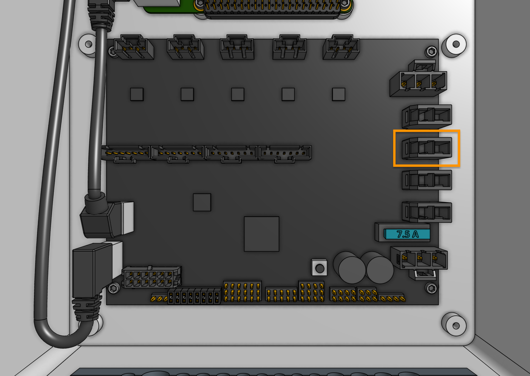
Connect the LED strip to the Agriduino peripheral connector labelled LIGHTING (directly underneath the water connector). The connector will only fit in one direction.
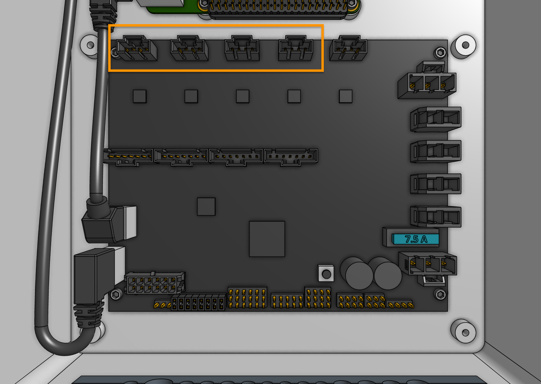
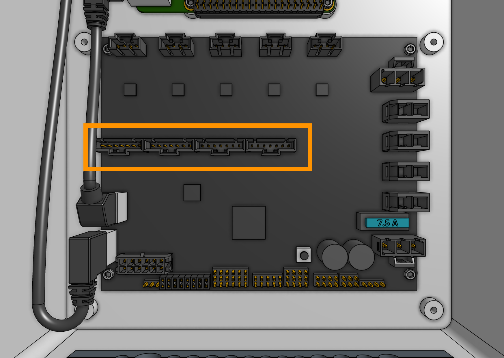
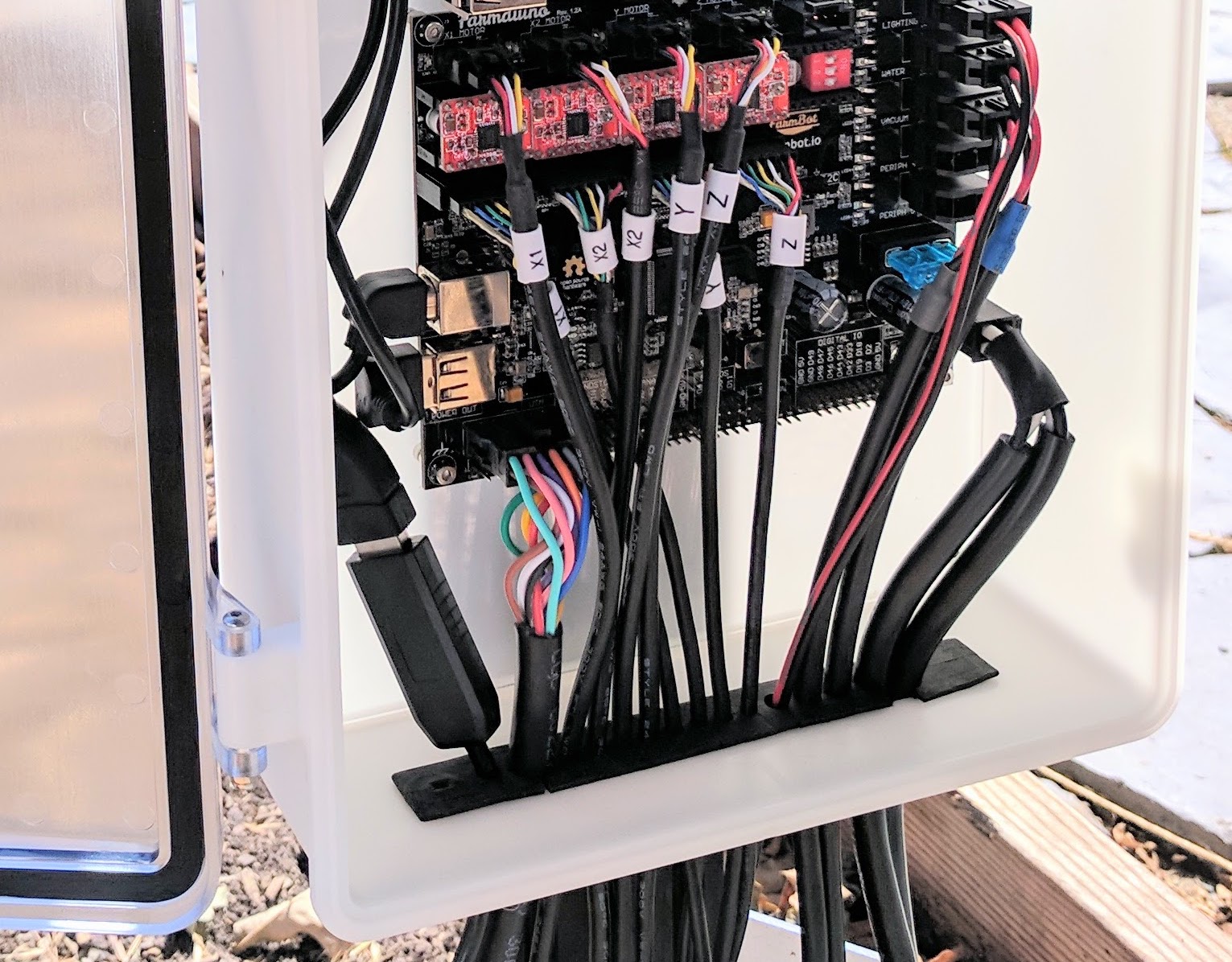
Step 3: Plug in the stepper motors and rotary encoders
Plug in the motor and encoder cables to the Agriduino.
Each cable is labelled with a white sleeve, which corresponds to the connectors on the Agriduino.
From left to right, the connectors on Agriduino are X1, X2, Y, and Z.
Each connector can only be inserted in one direction, and has a locking tab to prevent it from falling out.
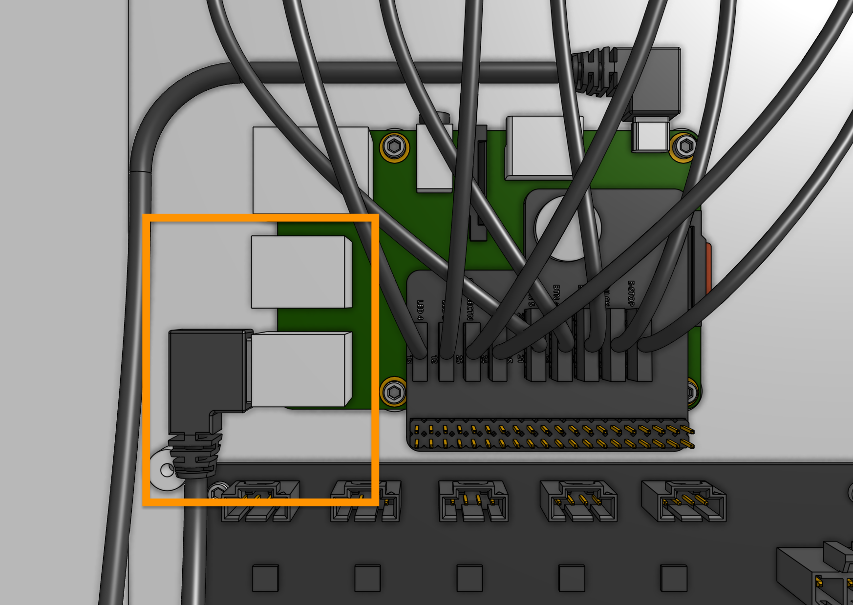
Step 4: Plug in the camera
Plug the camera cable into the Raspberry Pi. The exact USB port chosen does not matter.
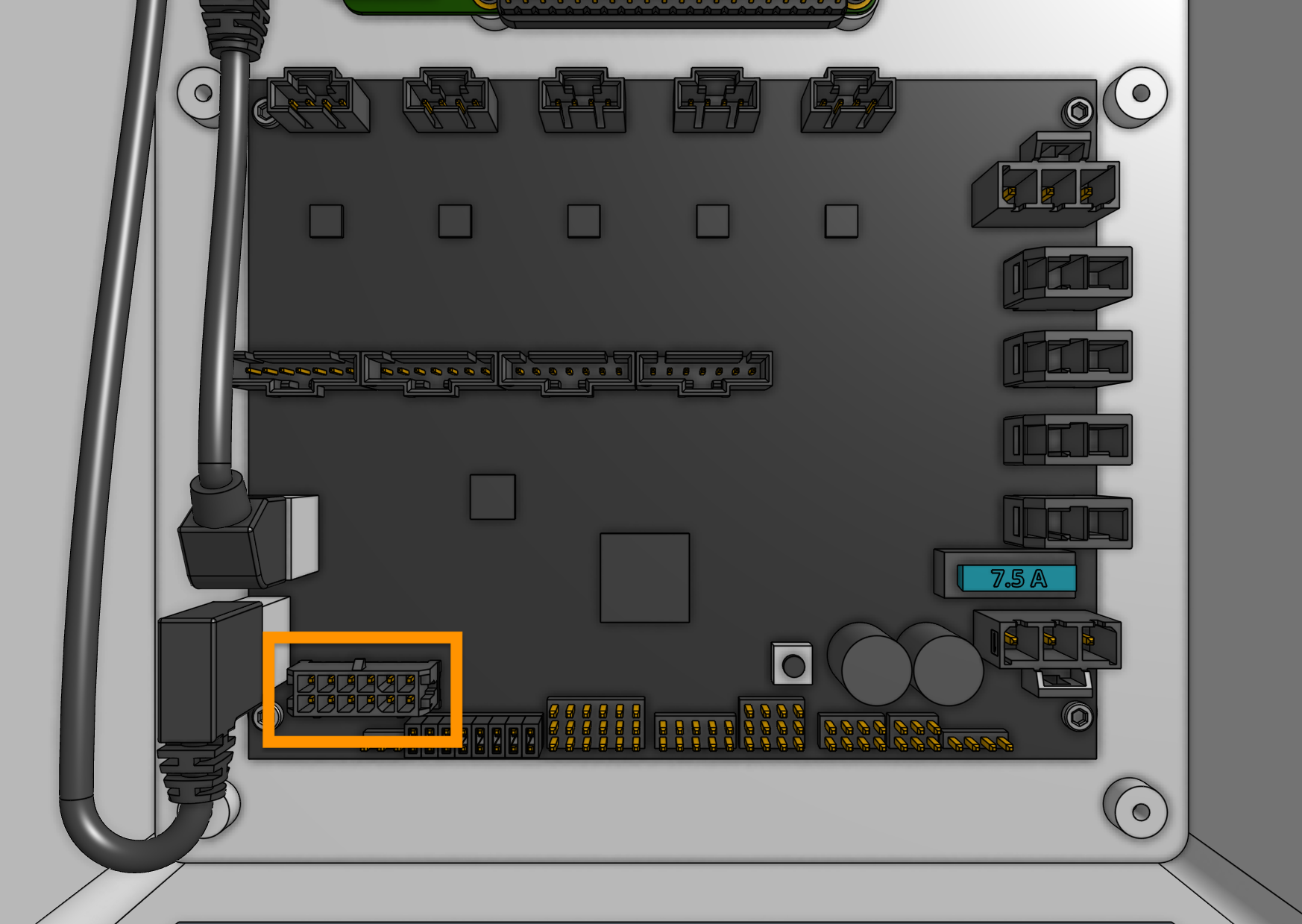
Step 5: Plug in the UTM cable
Plug in the UTM cable to the Agriduino. The connector will only fit in one direction.
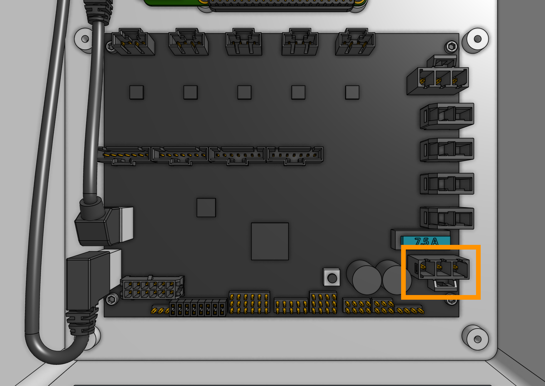
Step 6: Plug the power supply into the Agriduino
Connect the 3-pin power supply connector to the Agriduino’s power input. The connector will only fit in one direction.
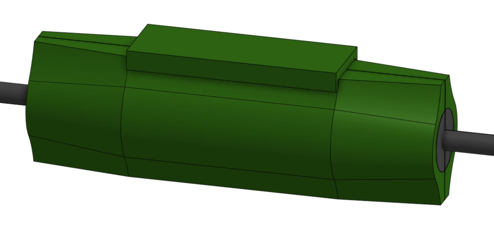
Step 7: Insert the supergland
Insert one half of the supergland into the slot in the bottom of the electronics box.
The left-most hole in the supergland should be small (it is for the camera) while the right-most hole should be medium-sized (it is for the power supply).
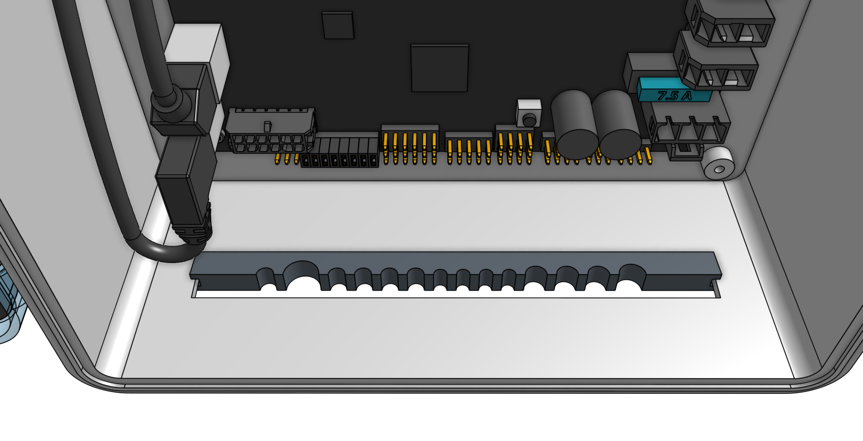
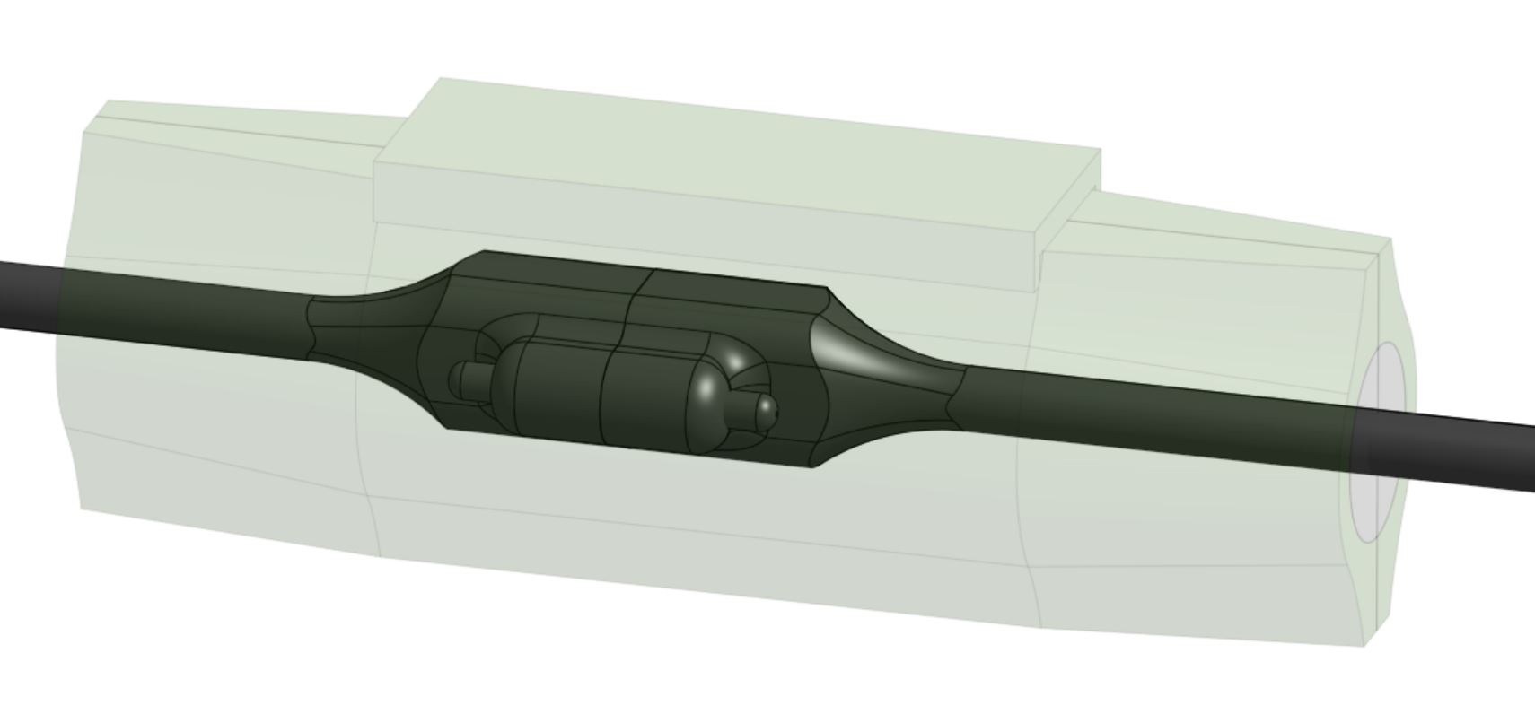
Organize and position the cables into the supergland. From left to right, the cables should be: camera, UTM, motors, encoders, peripherals, power supply.
Once the cables are all inserted into the first supergland half, gently insert the second half of the supergland into the slot in the electronics box.
Ensure that the flanges of both supergland halves are on either side of the electronics box wall.
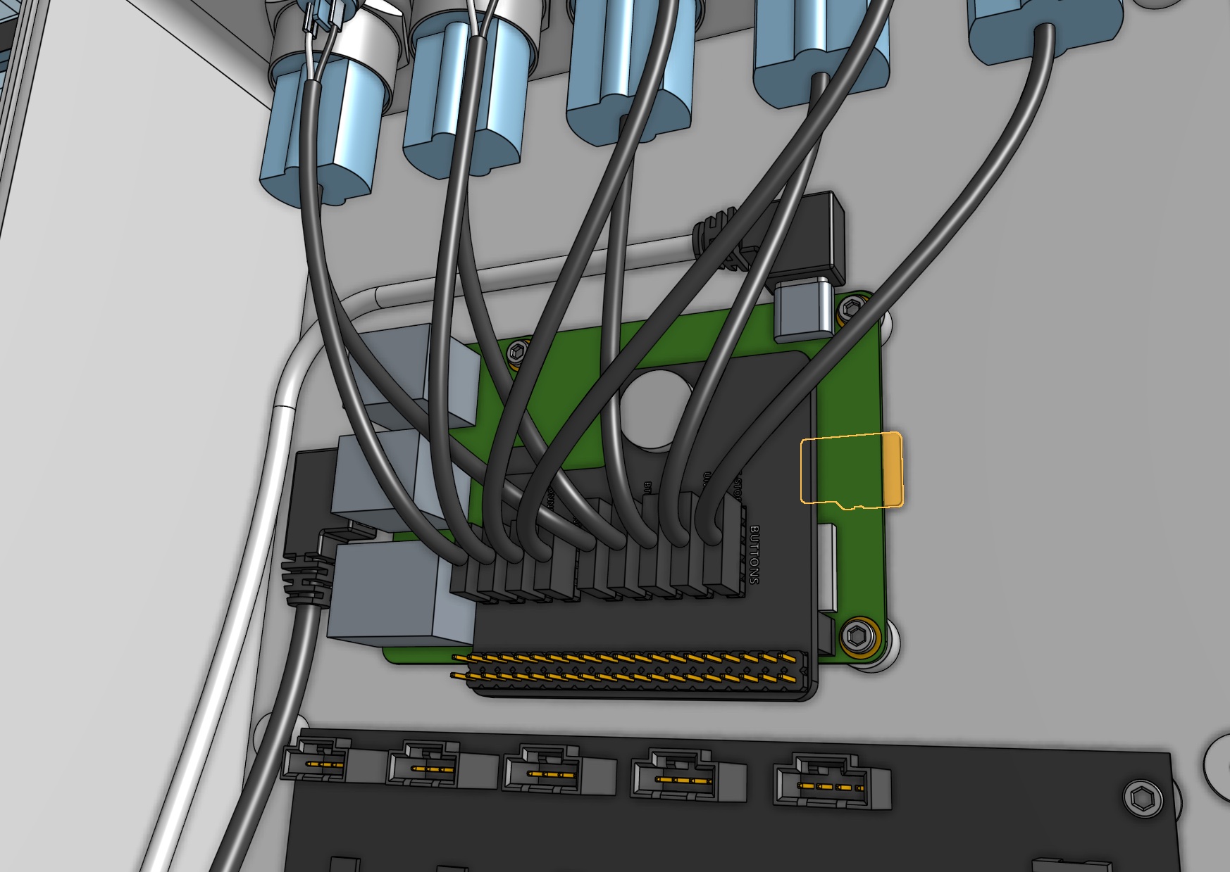
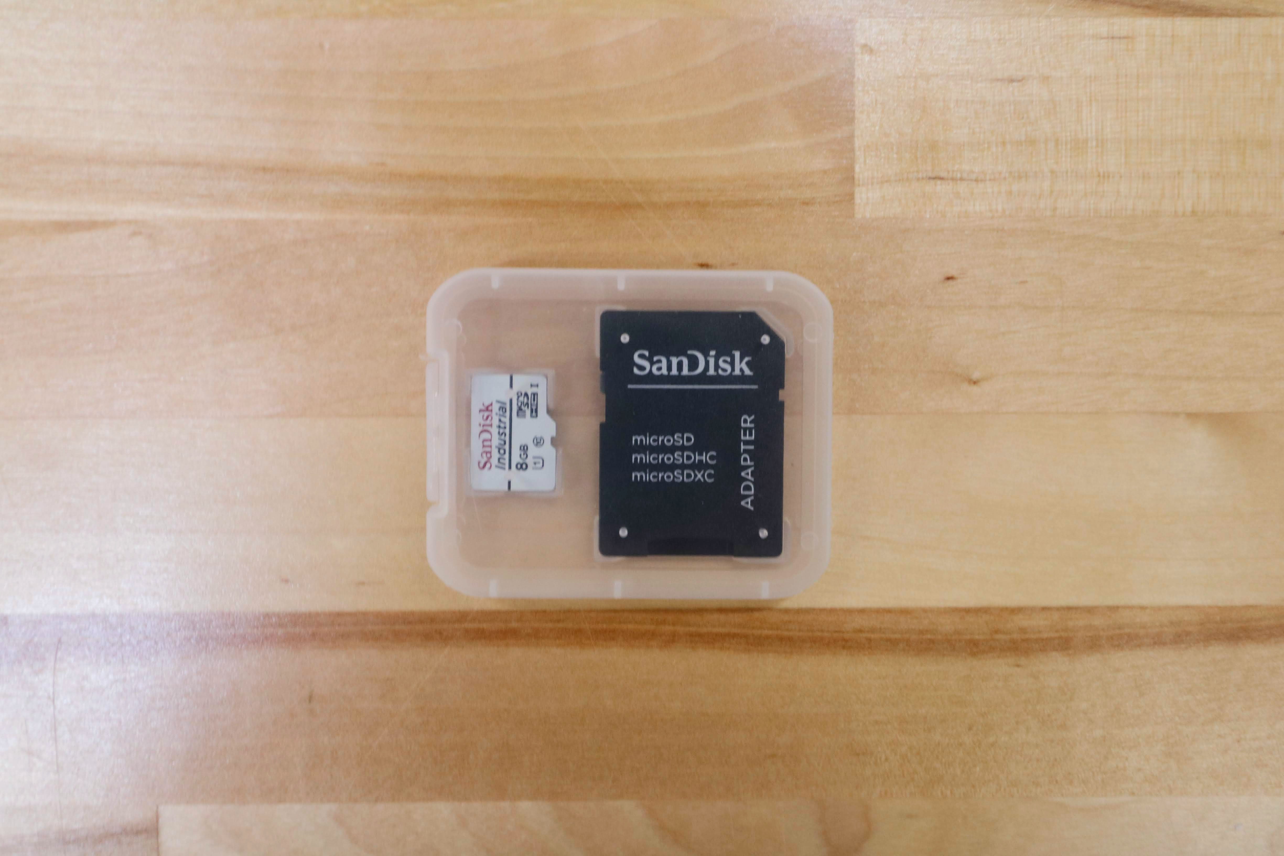
Step 8: Install AgriBot OS onto the microSD card
Follow these instructions on the software documentation hub to install AgriBot OS onto the micro SD card.
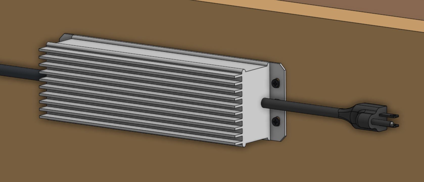
Step 9: Mount the power supply
Mount the power supply to your supporting infrastructure using four wood screws.
The power supply is IP67 rated, so it can withstand rain and the elements.
Step 10: Plug in the power supply
Connect the power supply cable to the power supply output.
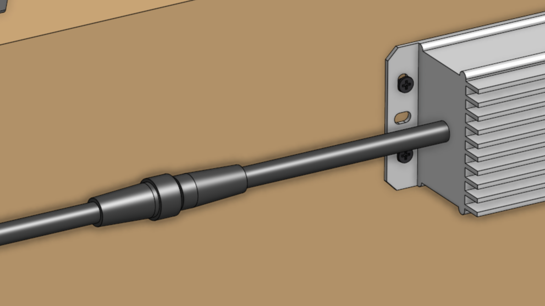
Before plugging the power supply into an outlet or an extension cord, please read the precaution below.
If everything looks good, and you understand the precautions needed around powered electronics, go ahead and plug the power supply into a GFCI outlet.
If an appropriate outlet is not close enough to plug in directly, use an extension cord and the provided green outdoor electrical connection protector.