Cables and Tubing
Installing the cables and tubing through AgriBot’s cable carriers can be a tedious process.
Take your time when installing the cables to ensure you complete this part of the assembly correct the first time, otherwise it might become frustrating if you need to re-do anything.
Cable carrier reference
Axis |
Size (85 links) |
Size (160 links) |
|---|---|---|
X |
|
|
Y |
|
|
Z |
|
|
Motor and encoder cable reference
Axis |
X1 |
X2 |
|---|---|---|
X |
0.7m |
2.3m |
X |
0.7m |
3.8m |
Y |
2.7m |
4.2m |
ZY |
2.6m |
4.1m |
ZZ |
1.8m |
1.8m |
Z-Axis Cable Carrier
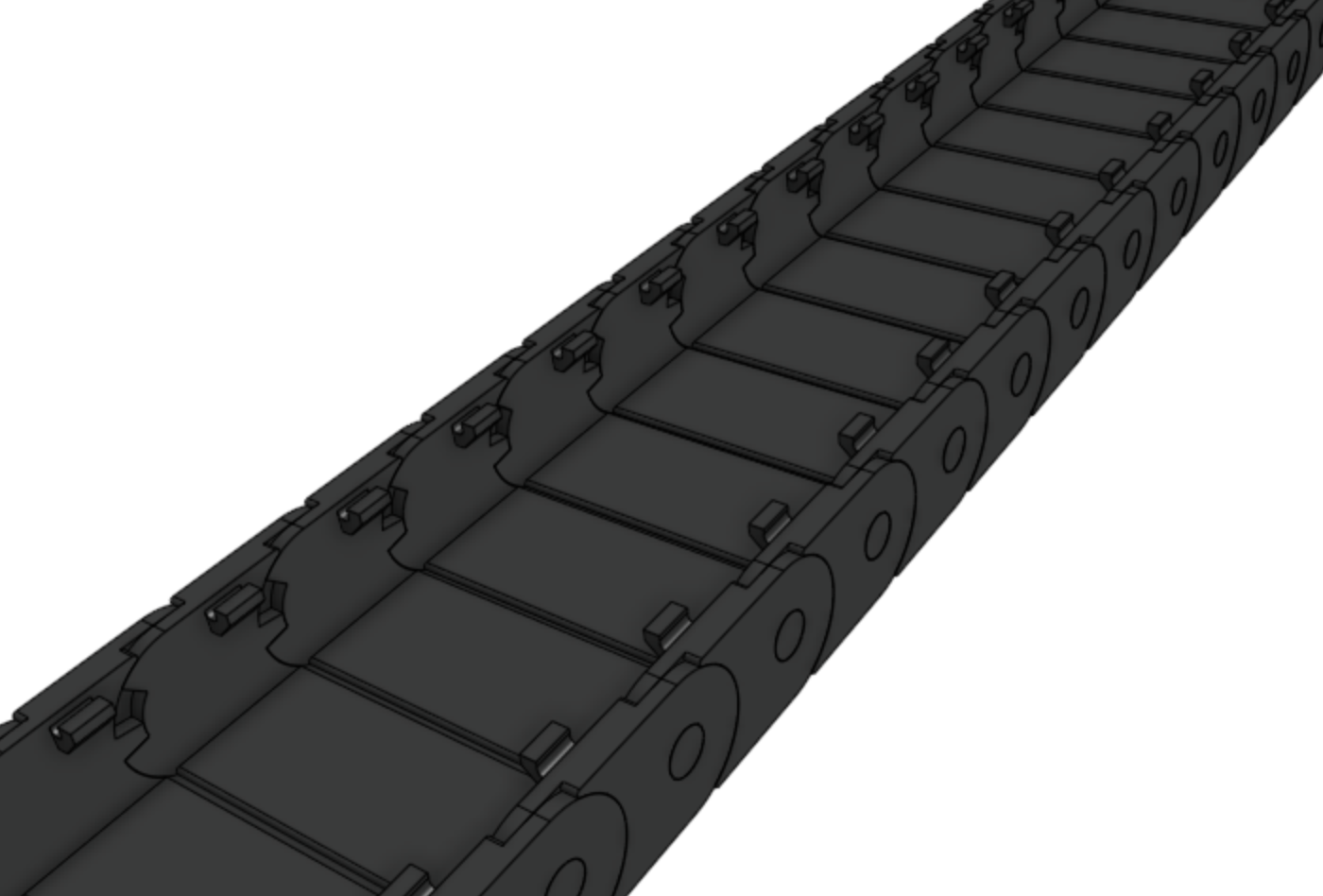
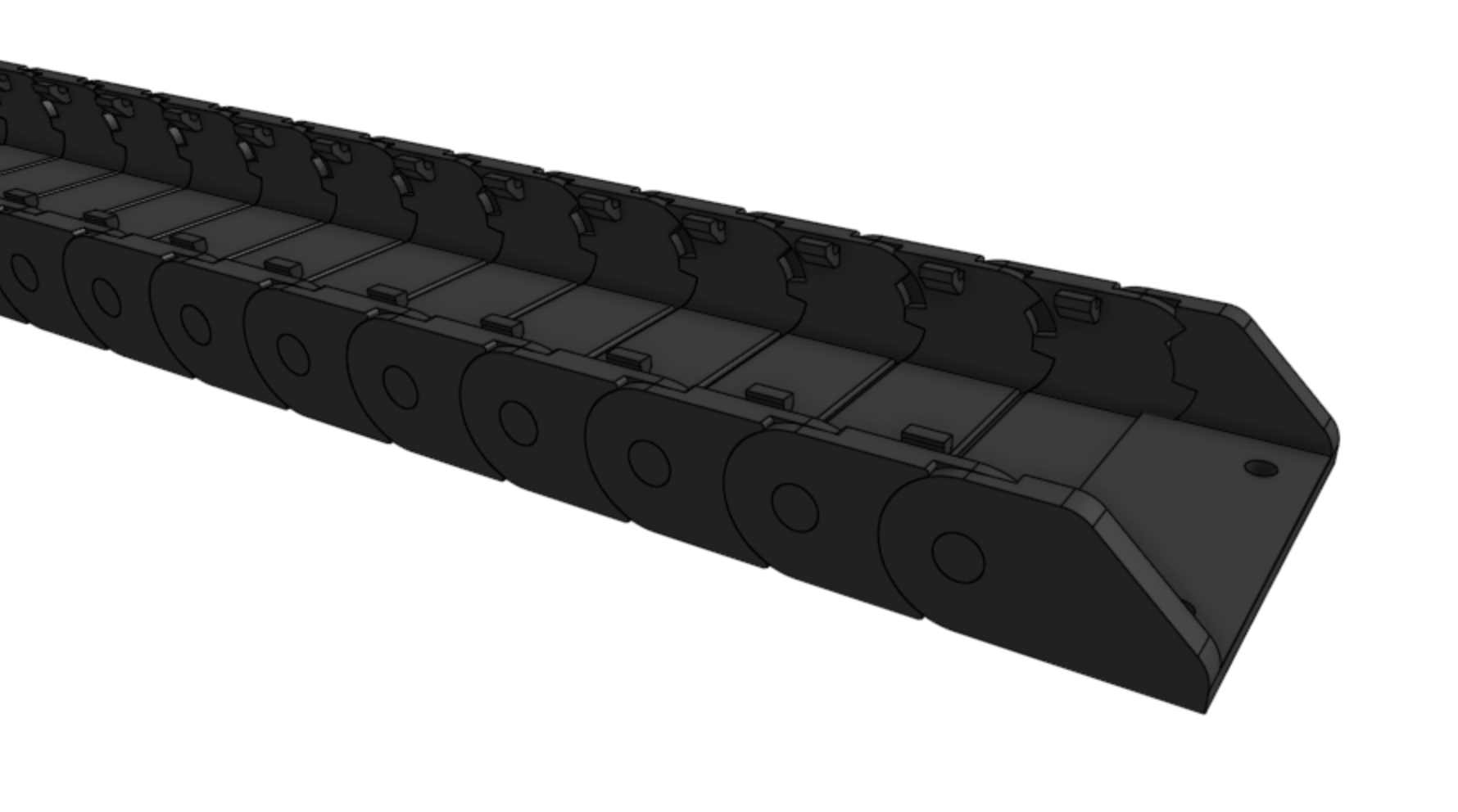
Step 1: Prepare the cable carrier
Remove all of the snap-in tabs from the z-axis cable carrier.
The z-axis cable carrier is the shortest cable carrier in the kit.
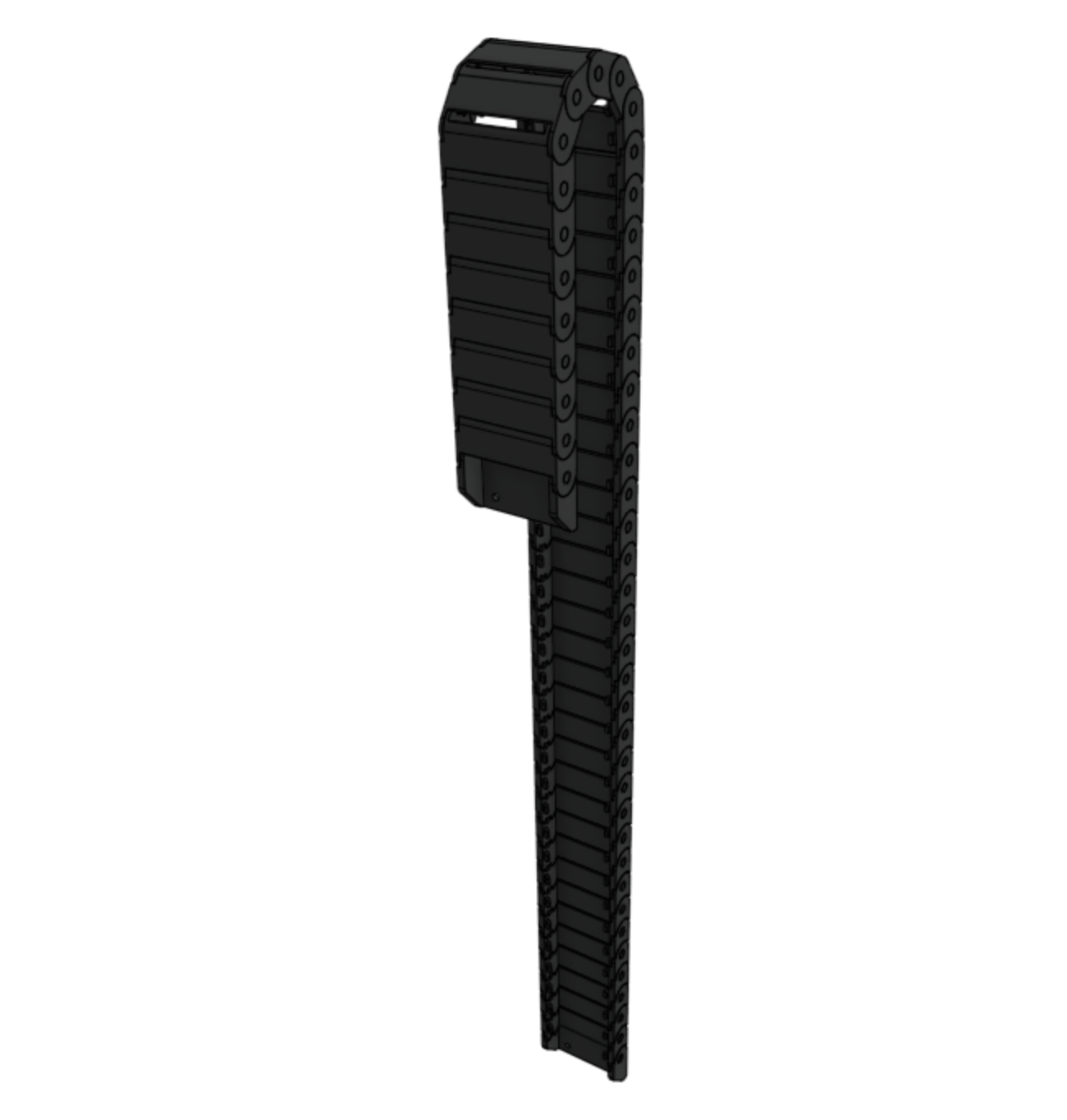
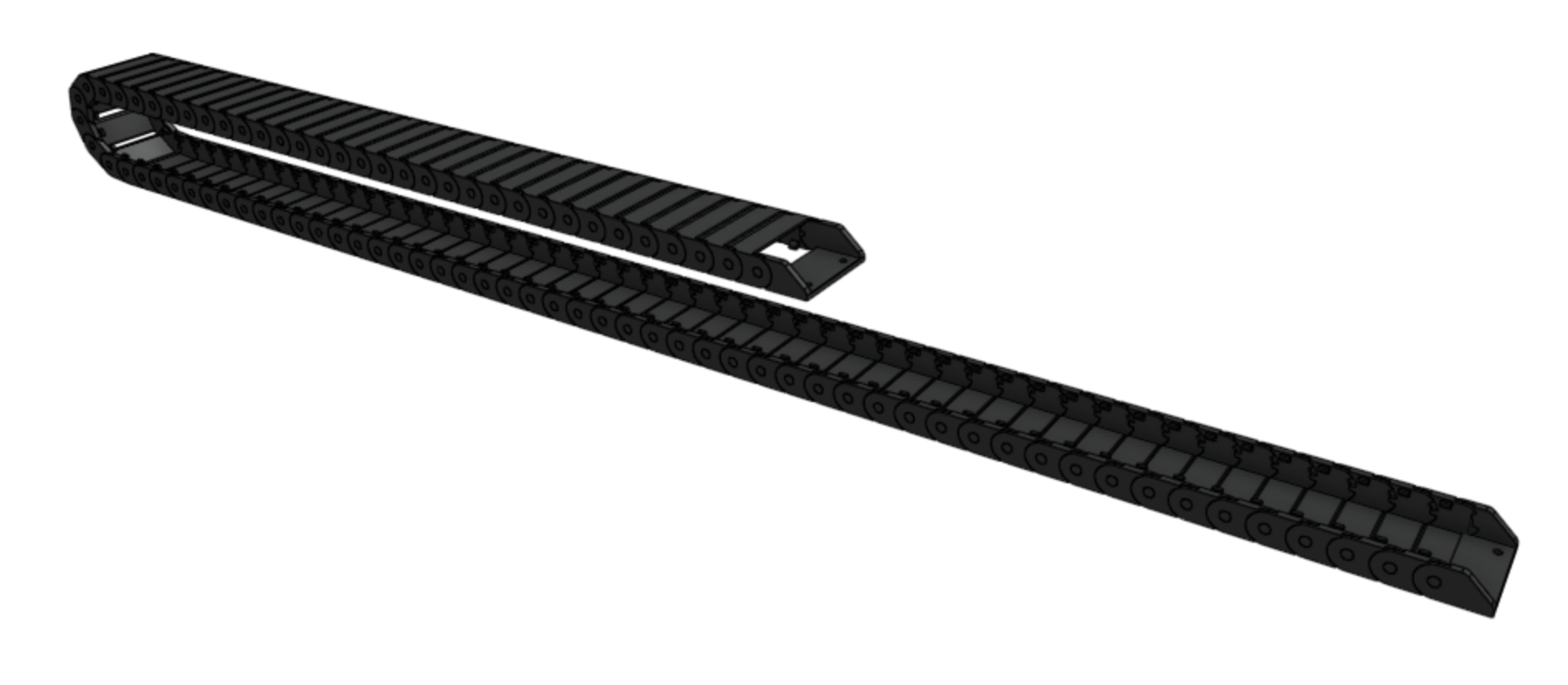
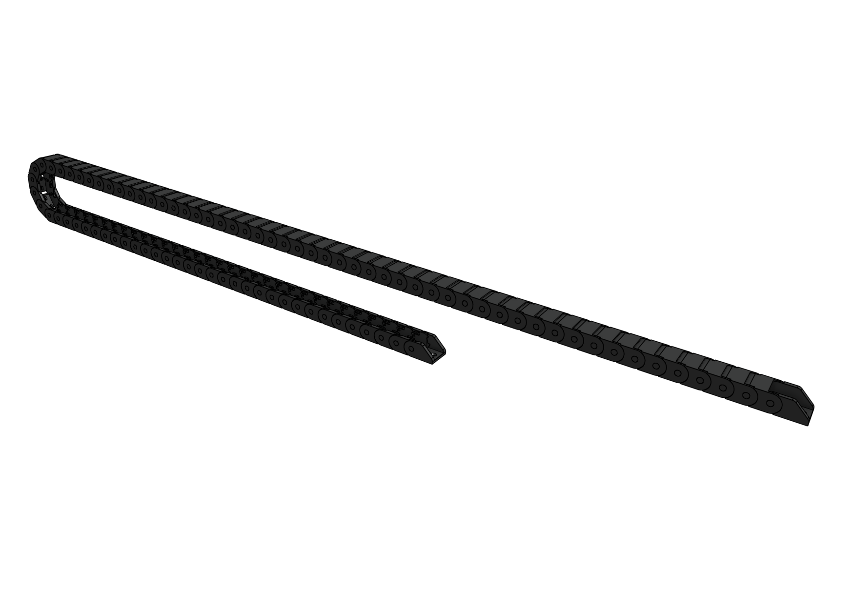
Step 2: Orient the cable carrier
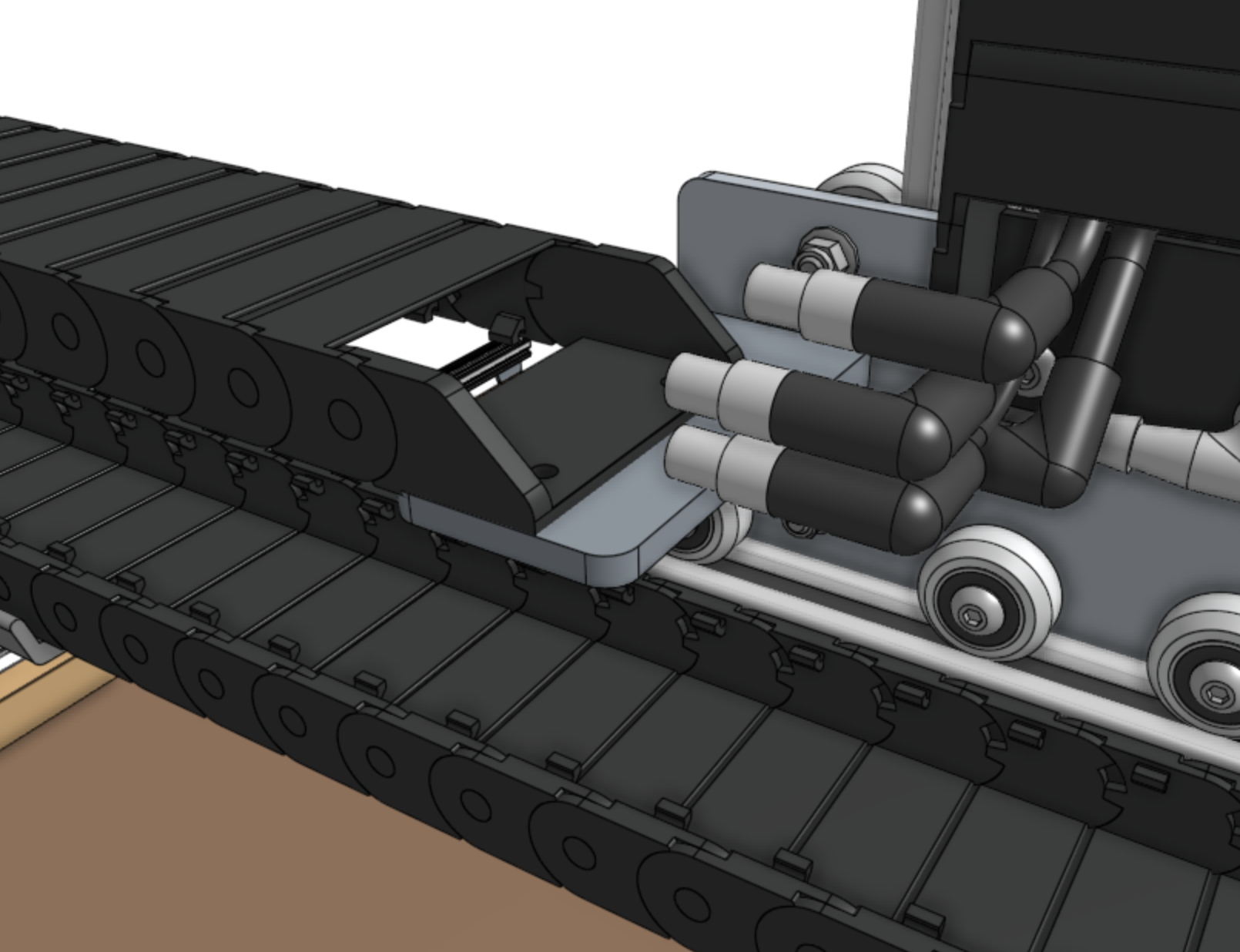
There is only one orientation that the z-axis cable carrier mounts to the cross-slide and z-axis, and it is determined by the orientation of the end pieces.
Inspect the images below to see how the cable carrier will be mounted, but do not attach it at this time.
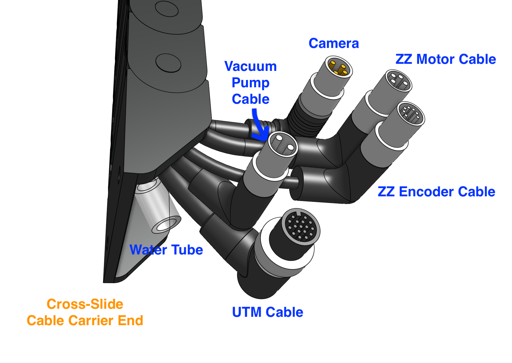
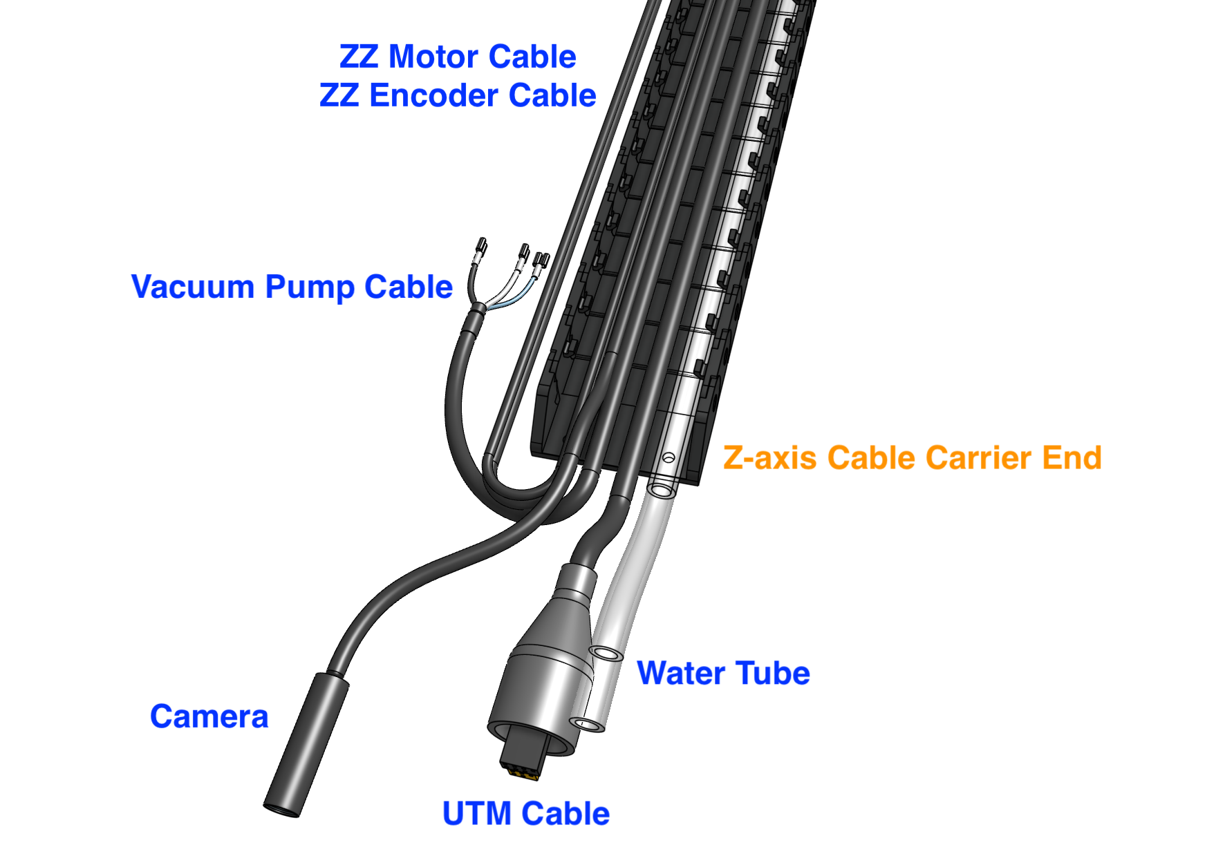
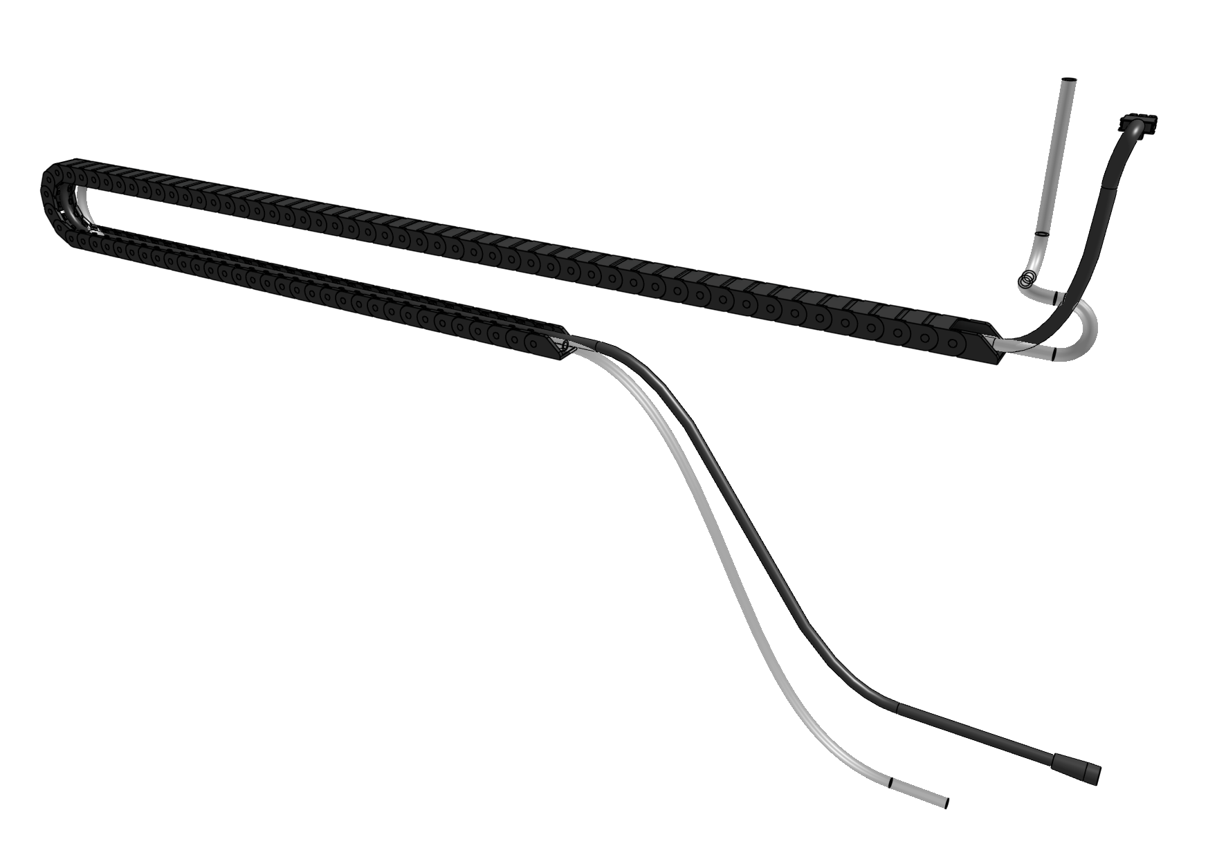
Step 3: Lay everything into the cable carrier
Keeping the mounting orientation of the cable carrier in mind, lay the following items into the open cable carrier.
The cross-slide end of all items should be sticking out from the cross-slide end of the cable carrier by approximately 5cm.
This will leave the appropriate remaining length of each item sticking out from the z-axis end of the cable carrier.
Item |
Cross-slide end description |
|---|---|
Z-axis water tube (0.95m long) |
Either |
Z-axis UTM cable (1.0m long) |
End with 90-degree connector |
Camera (1.0m long) |
End with 90-degree connector |
Z vacuum pump cable (1.0m long) |
End with 90-degree connector |
ZZ motor cable (1.8m long) |
End with 90-degree connector |
ZZ encoder cable (1.8m long) |
End with 90-degree connector |
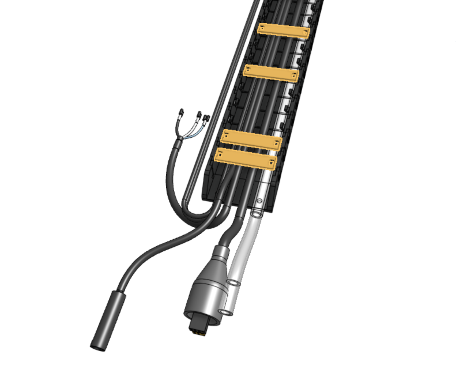
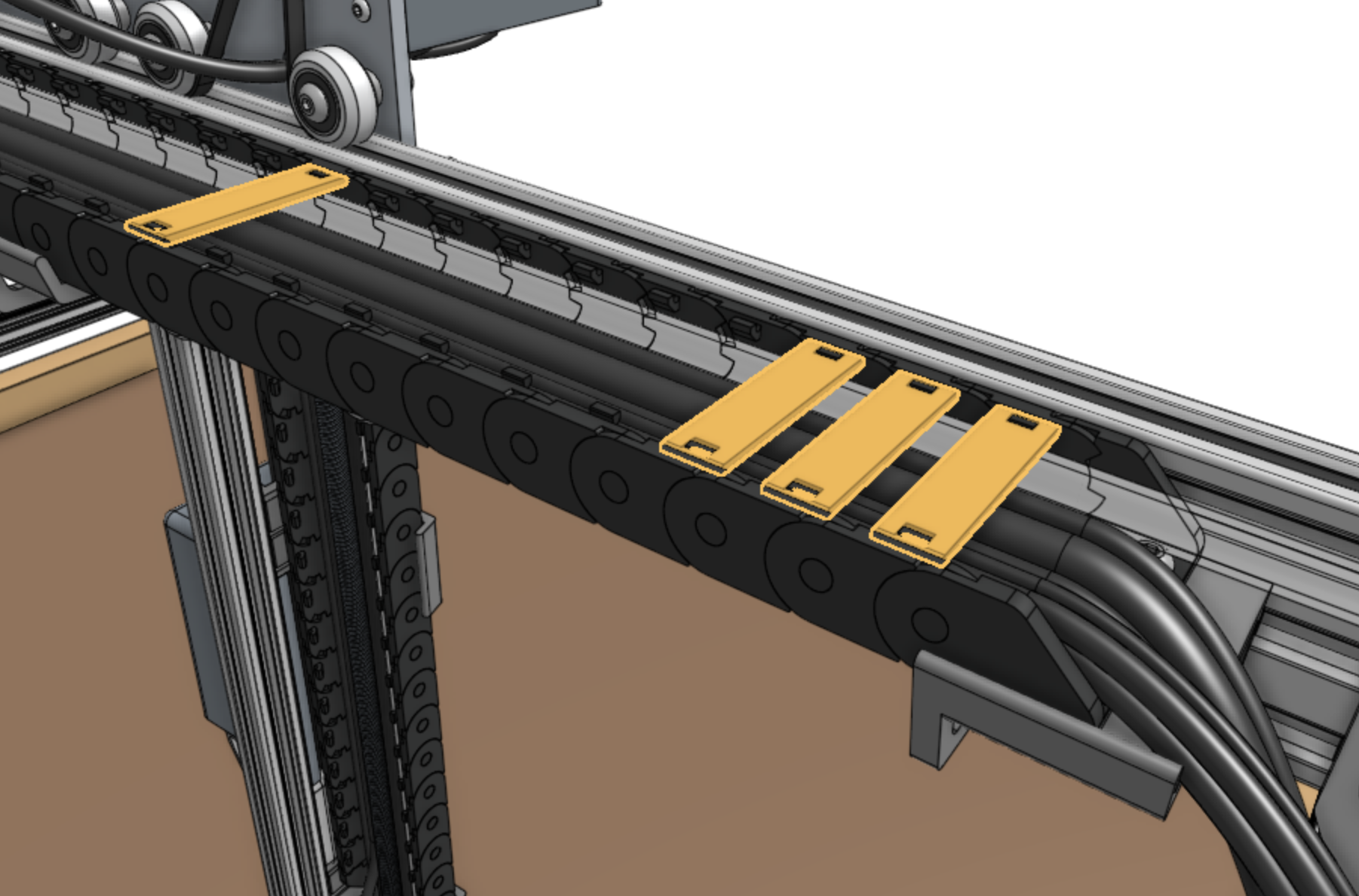
Step 4: Snap in some tabs
Snap in three cable carrier tabs at both ends of the cable carrier, and a handful more spread throughout the middle so that as you mount the assembly, the cables and tubing will stay in place.
Do not snap in all of the tabs at this time because that will make it difficult to make adjustments if needed.
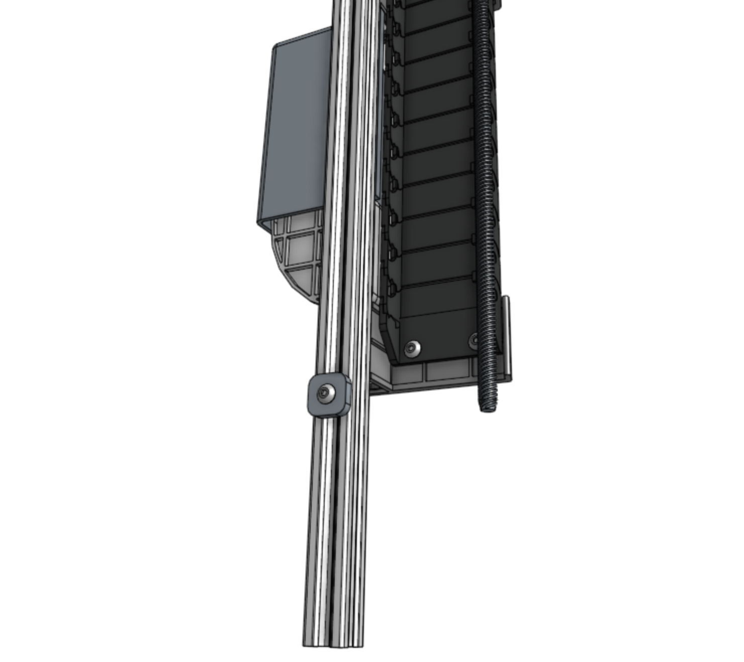
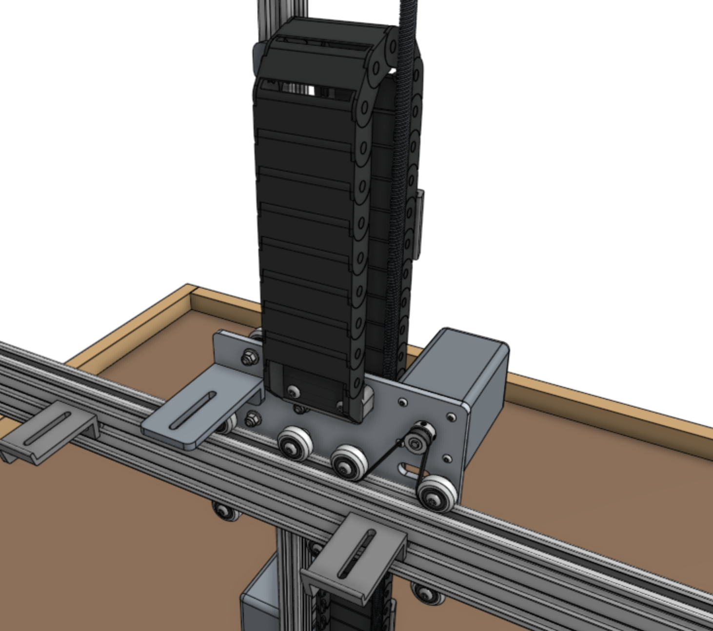
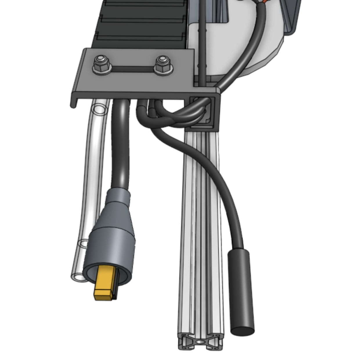
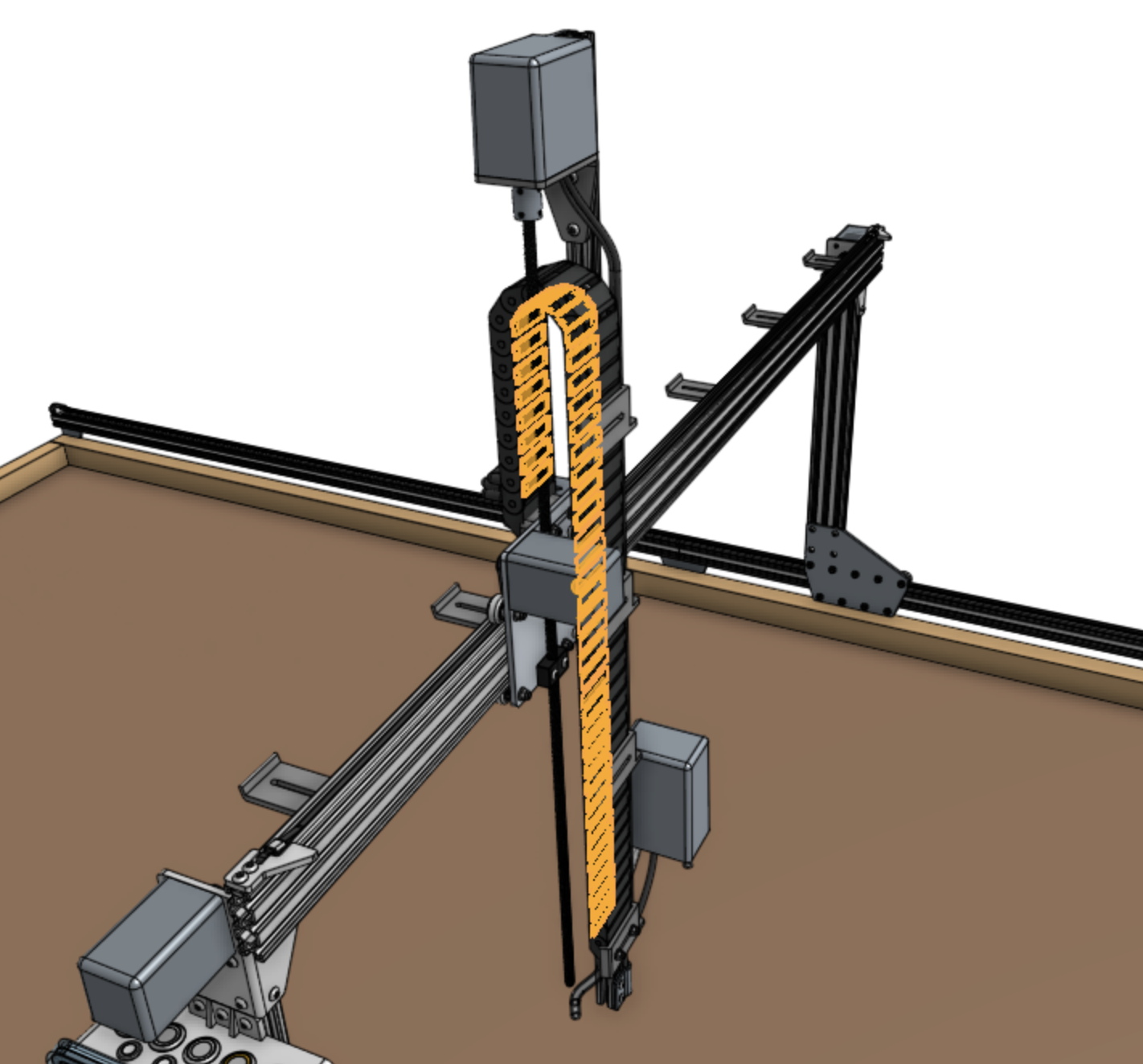
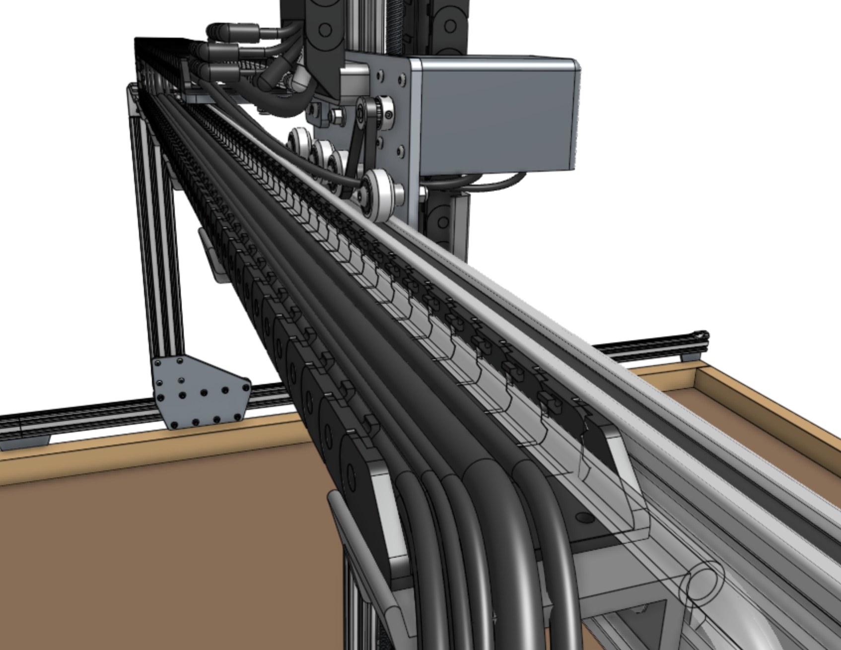
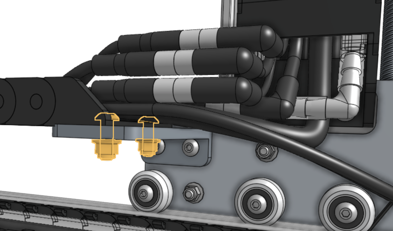
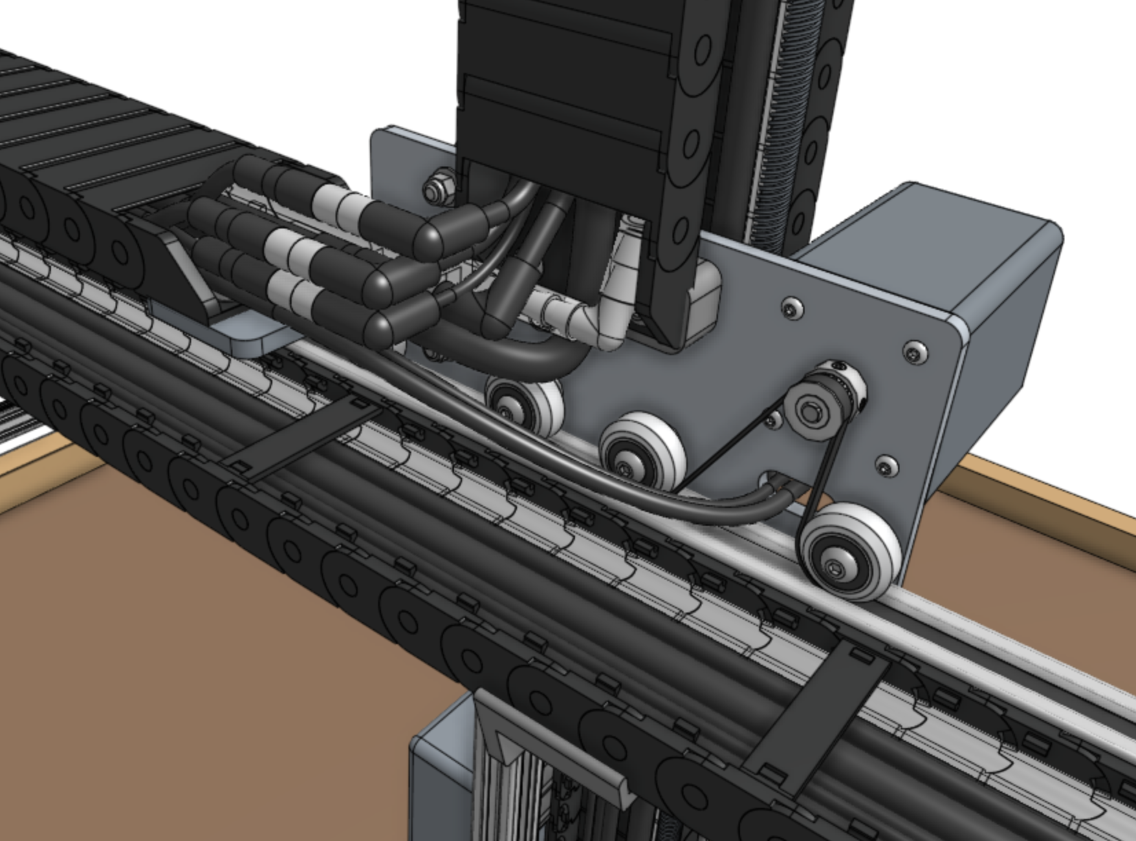
Step 5: Mount the cable carrier
Carefully drape the cable carrier assembly into position.
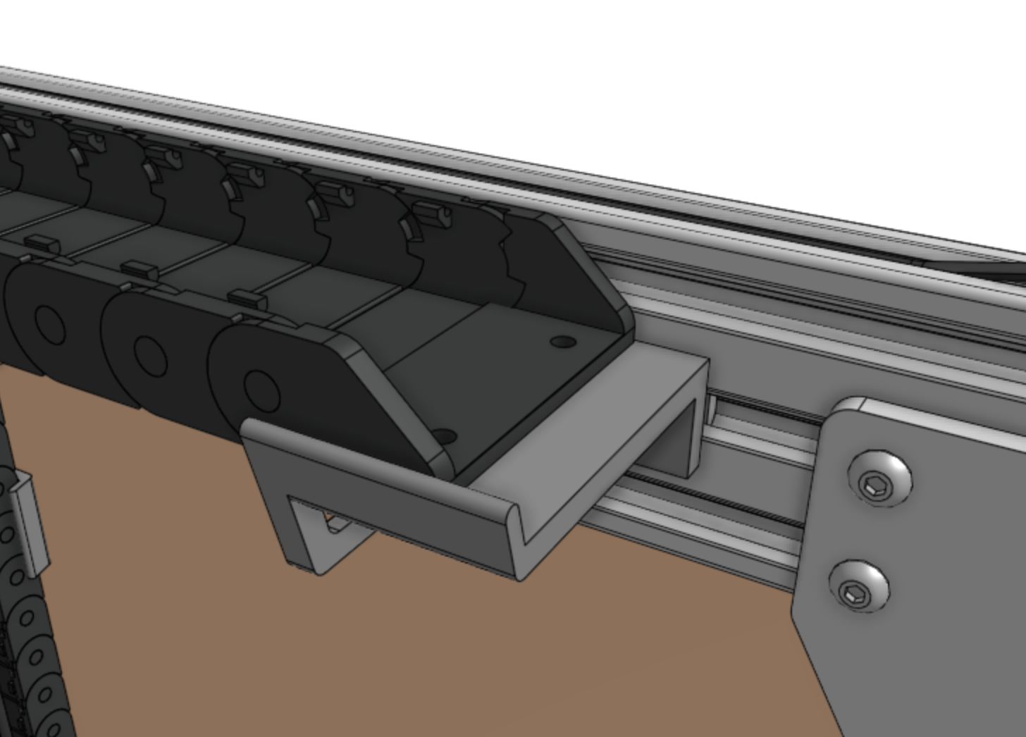
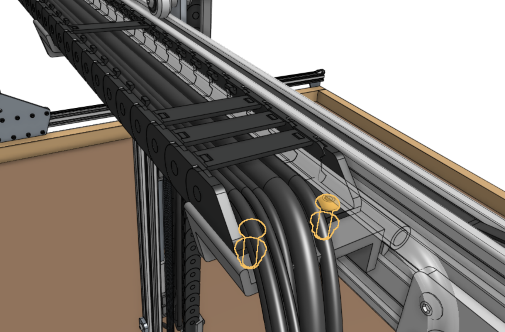
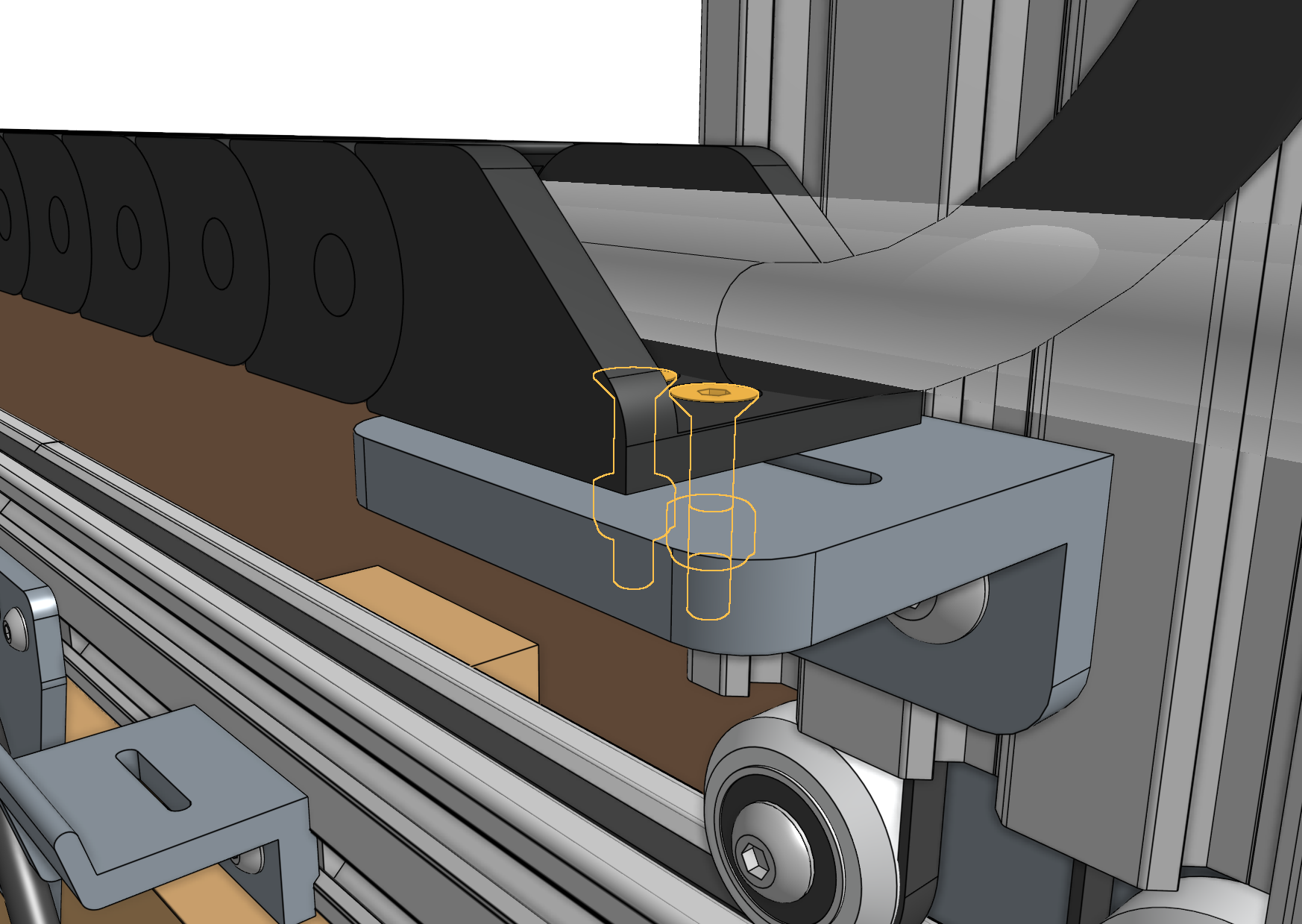
Attach the cross-slide end of the cable carrier to the cross-slide using two M5 x 30mm screws, M5 flange locknuts, and the cable carrier spacer block.
The screws should thread firmly through the cable carrier end piece.
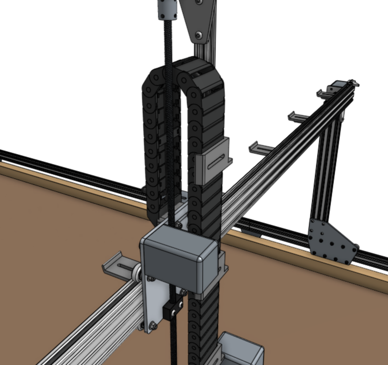
Now attach the z-axis end of the cable carrier to the lowest vertical cable carrier support on the z-axis using two M5 x 16mm screws and M5 flange locknuts.
The screws should thread firmly through the cable carrier end piece.
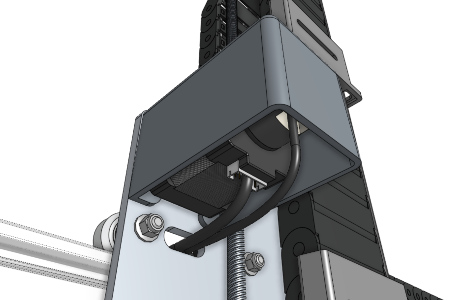
Step 6: Connect the z-axis motor and encoder
Feed the ZZ motor and encoder cables up through the slots in the vertical cable carrier supports, and then through the slot in the z-axis motor mount.
Then connect the cables to the motor and encoder.
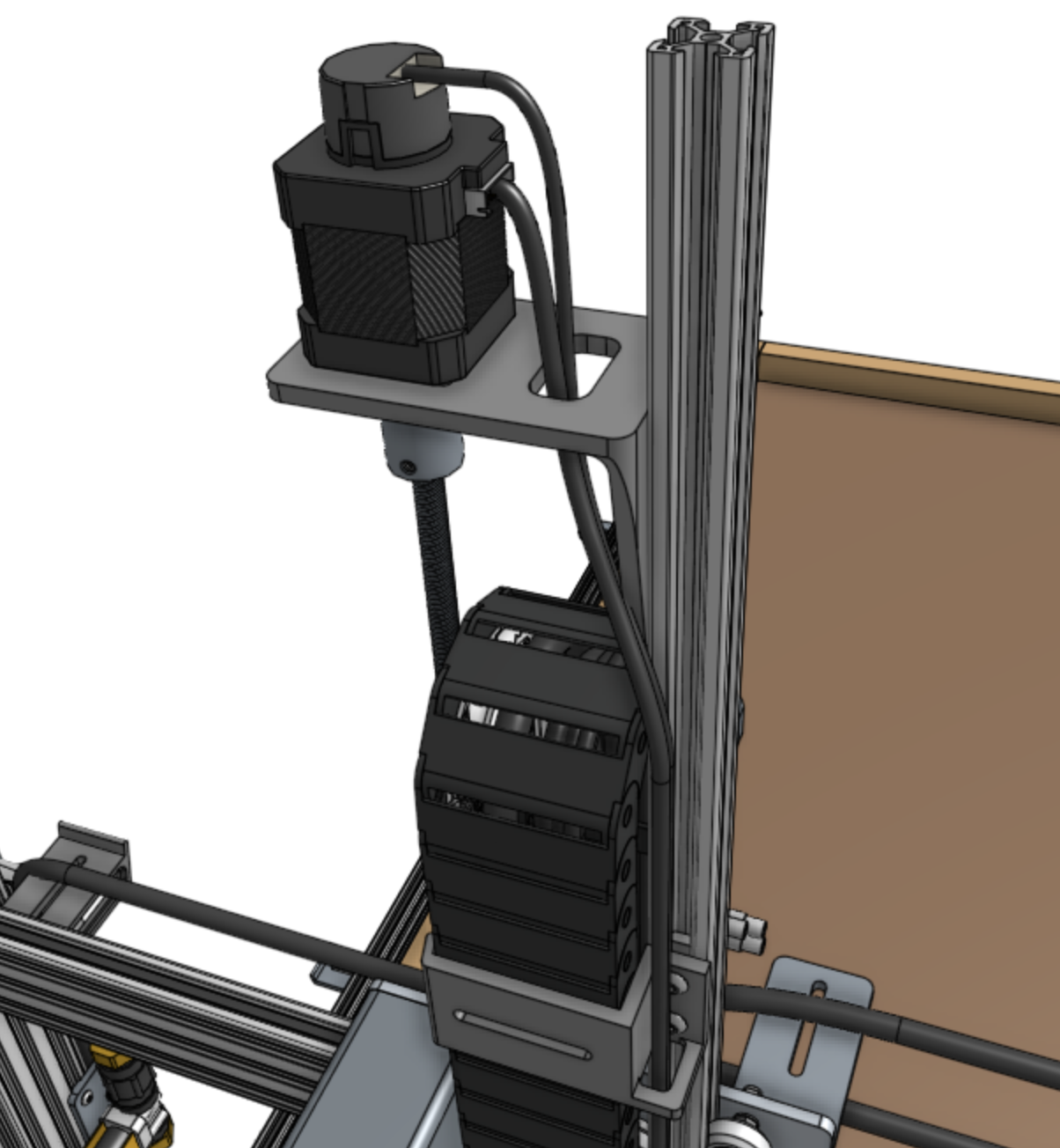
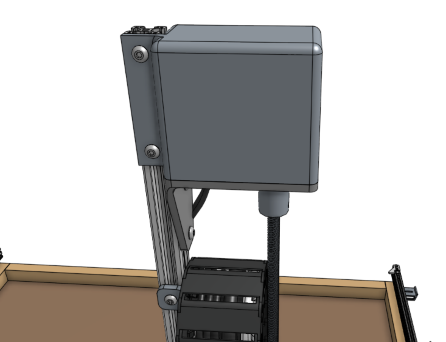
Step 7: Add the vertical motor housing
Attach the vertical motor housing to the z-axis extrusion using M5 x 10mm screws and tee nuts.
Step 8: Snap in the remaining tabs
Once everything is situated well, snap-in the remaining cable carrier tabs, ensuring that you maintain organization of the cables and tube.
Y-Axis Cable Carrier
Step 1: Prepare the cable carrier
Remove all of the snap-in tabs from the y-axis cable carrier.
Note that the x-axis and y-axis cable carriers are the same length, but the y-axis cable carrier is wider than the x-axis one.
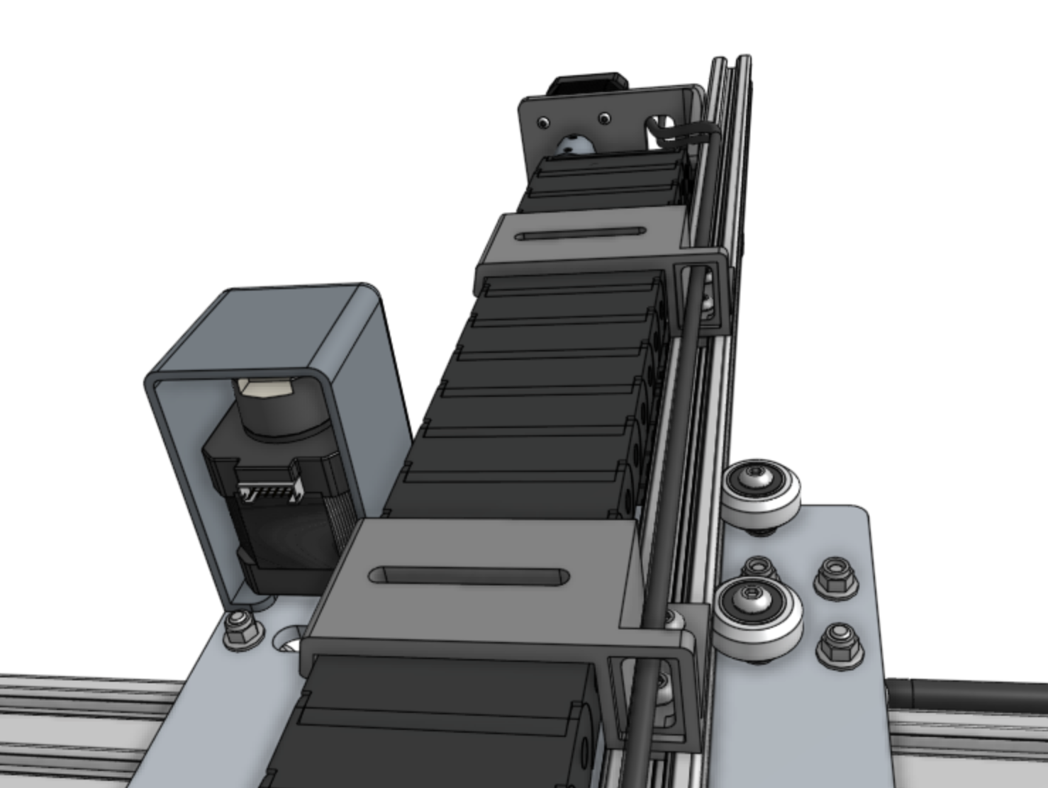
Step 2: Orient the cable carrier
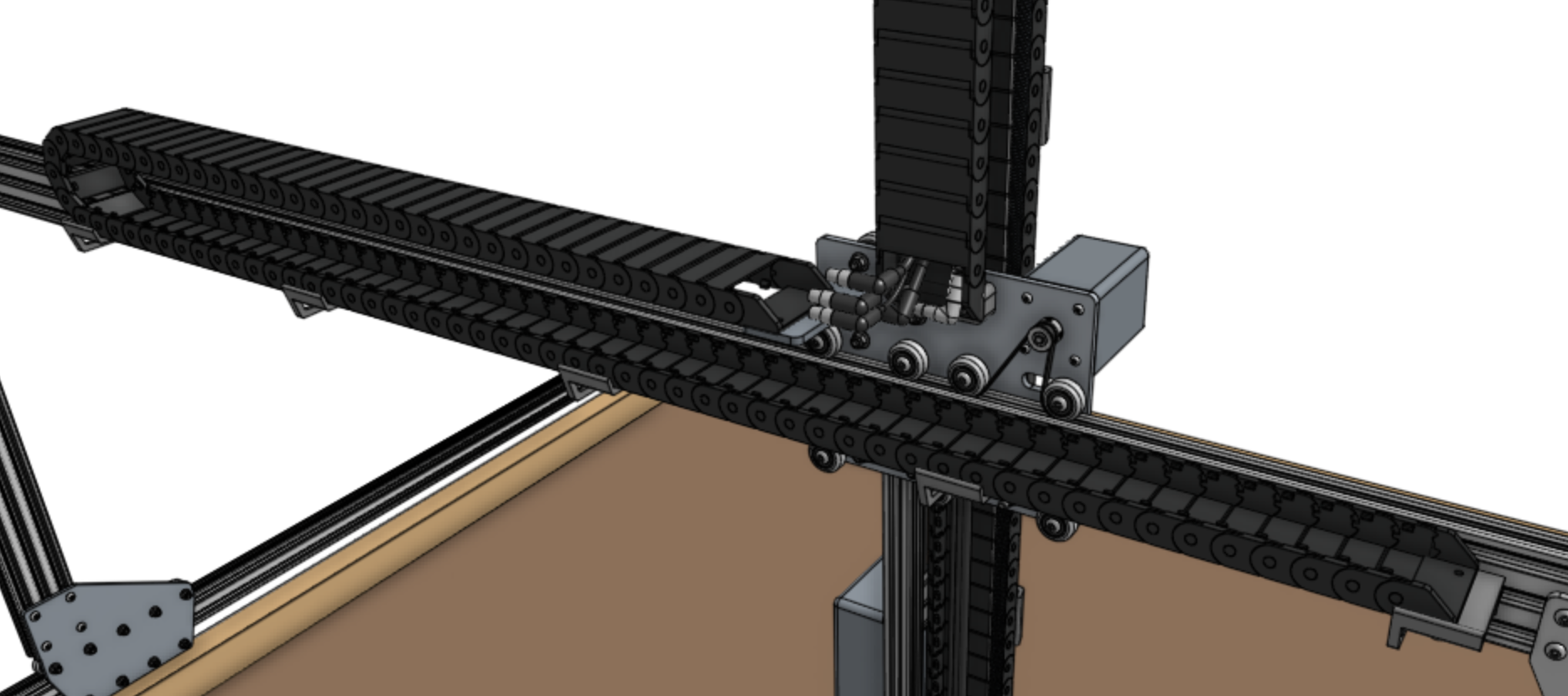
There is only one orientation that the y-axis cable carrier mounts to the cross-slide and gantry, and it is determined by the orientation of the end pieces.
Lay the cable carrier onto the gantry’s horizontal cable carrier supports but do not attach it at this time.
Step 3: Add the y-axis motor and encoder cables
Feed the y-axis motor and encoder cables through the slot in the cross-slide plate such that there is enough cable length so that they can be comfortably connected to the motor and encoder.
Ensure you feed the correct end of the cables through the slot by checking the connection with the y-axis motor and encoder.
However, do not keep them plugged in at this time as they can be damaged if pulled on.

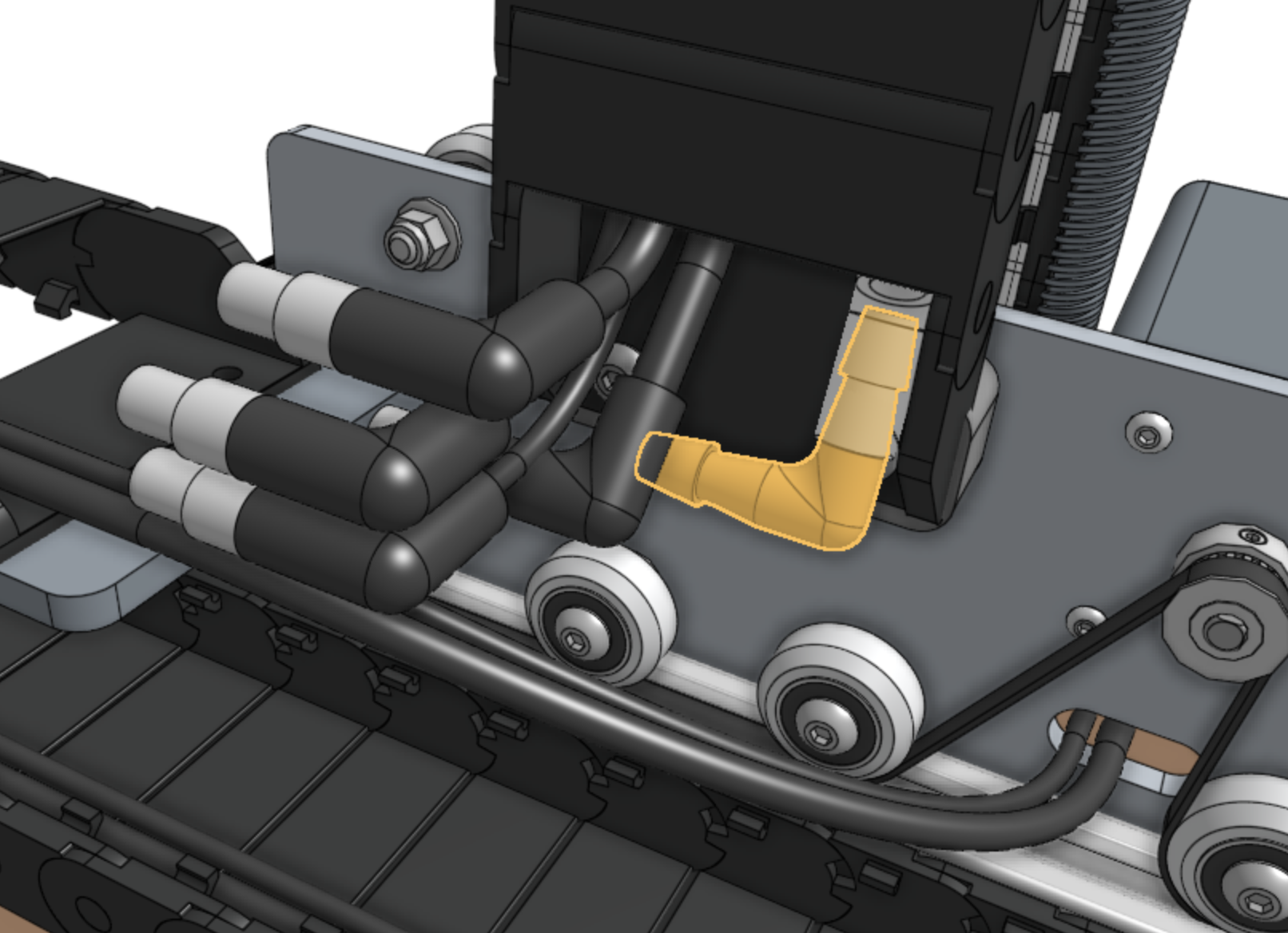
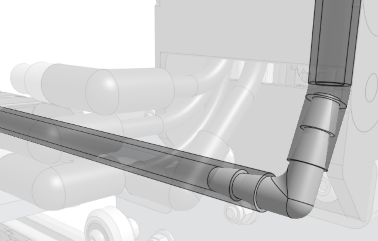
Step 4: Connect the tubing
Push the 90 degree barb onto the z-axis water tube.
Then push the y-axis water tube onto the other end of the barb.
Step 5: Connect the cabling
Connect the z-axis and y-axis sections of the following cables together:
Vacuum pump cable (Z) to vacuum pump cable (Y) with the 4-pin connector
ZZ encoder cable to ZY encoder cable with the 7-pin connector
ZZ motor cable to ZY motor cable with the 4-pin connector
UTM cable (Z) to UTM cable (Y) with the 12-pin connector
Camera to camera cable with the 4-pin connector
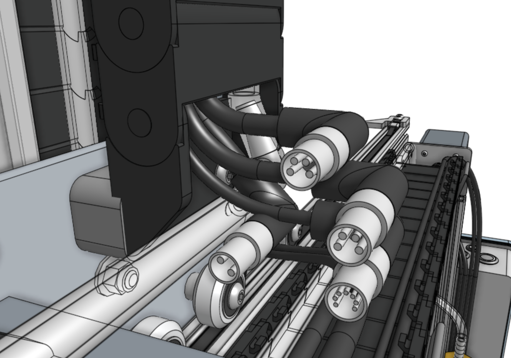
Pay special attention that you fully insert the 90-degree connectors together.
This may require a multi-step process of pushing together, slightly tightening the thumb screws, pushing together again, and tightening some more.
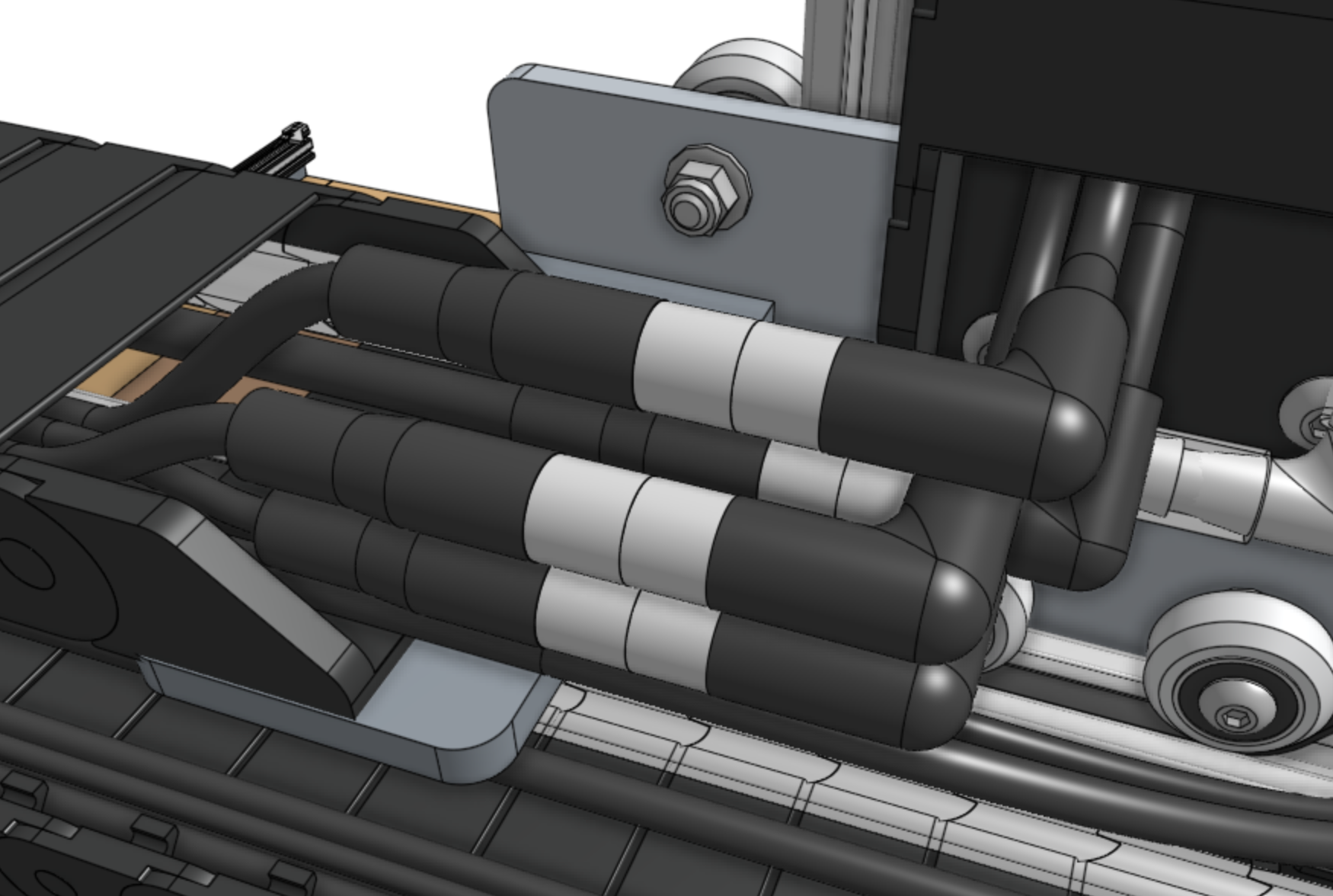
Step 6: Lay everything into the cable carrier
Neatly lay everything into the y-axis cable carrier:
Y motor cable
Y encoder cable
ZY motor cable
ZY encoder cable
Water tube (y-axis section)
UTM cable (y-axis section)
Camera cable (y-axis section)
Vacuum pump cable (y-axis section)
Step 7: Snap in some tabs
Snap in three cable carrier tabs at both ends of the cable carrier, and ten more spread throughout the middle of the cable carrier so that as you mount the assembly, the cables and tube will stay in place.
You do not want to snap in all of the tabs at this time because that will make it difficult to adjust anything if needed.
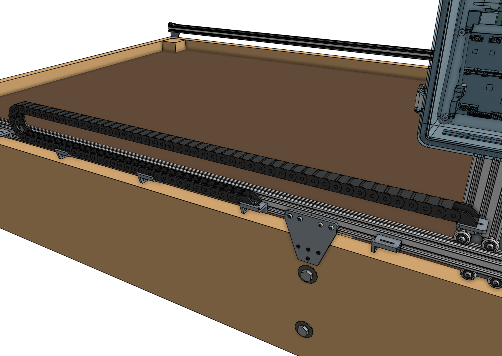
Step 8: Mount the cable carrier
Attach the y-axis cable carrier to the 80mm cable carrier mount using two M5 x 16mm screws and M5 flange locknuts.
The screws should thread firmly through the cable carrier end piece.
Reduce the amount of extra tubing and wiring between the y-axis cable carrier and the z-axis cable carrier by gently pulling any extra cable or tubing length through the y-axis cable carrier.
It can be difficult to coax the contents around the bend of the cable carrier, so take your time and ensure that you are not pulling anything too hard.
Attach the y-axis cable carrier to the 60mm horizontal cable carrier support nearest the left gantry column using two M5 x 16mm screws and M5 flange locknuts.
The screws should thread firmly through the cable carrier end piece.
Step 9: Snap in the remaining tabs
Once everything is situated well, snap-in the remaining cable carrier tabs, ensuring that you maintain organization of the cables and tube.
Step 10: Connect the y-axis motor and encoder
Connect the y-axis motor and encoder cables to the y-axis motor and encoder.

X-Axis Cable Carrier
Step 1: Prepare the cable carrier
Remove all of the snap-in tabs from the x-axis cable carrier.
Note that the x-axis and y-axis cable carriers are the same length, but the x-axis cable carrier is narrower than the y-axis one.
Step 2: Orient the cable carrier
There is only one orientation that the x-axis cable carrier mounts to the gantry and tracks, and it is determined by the orientation of the end pieces.
Lay the cable carrier onto the track’s horizontal cable carrier supports to ensure you have it correctly oriented. Do not attach it at this time.
Step 3: Lay everything into the cable carrier
Disconnect the power supply cable from the power supply.
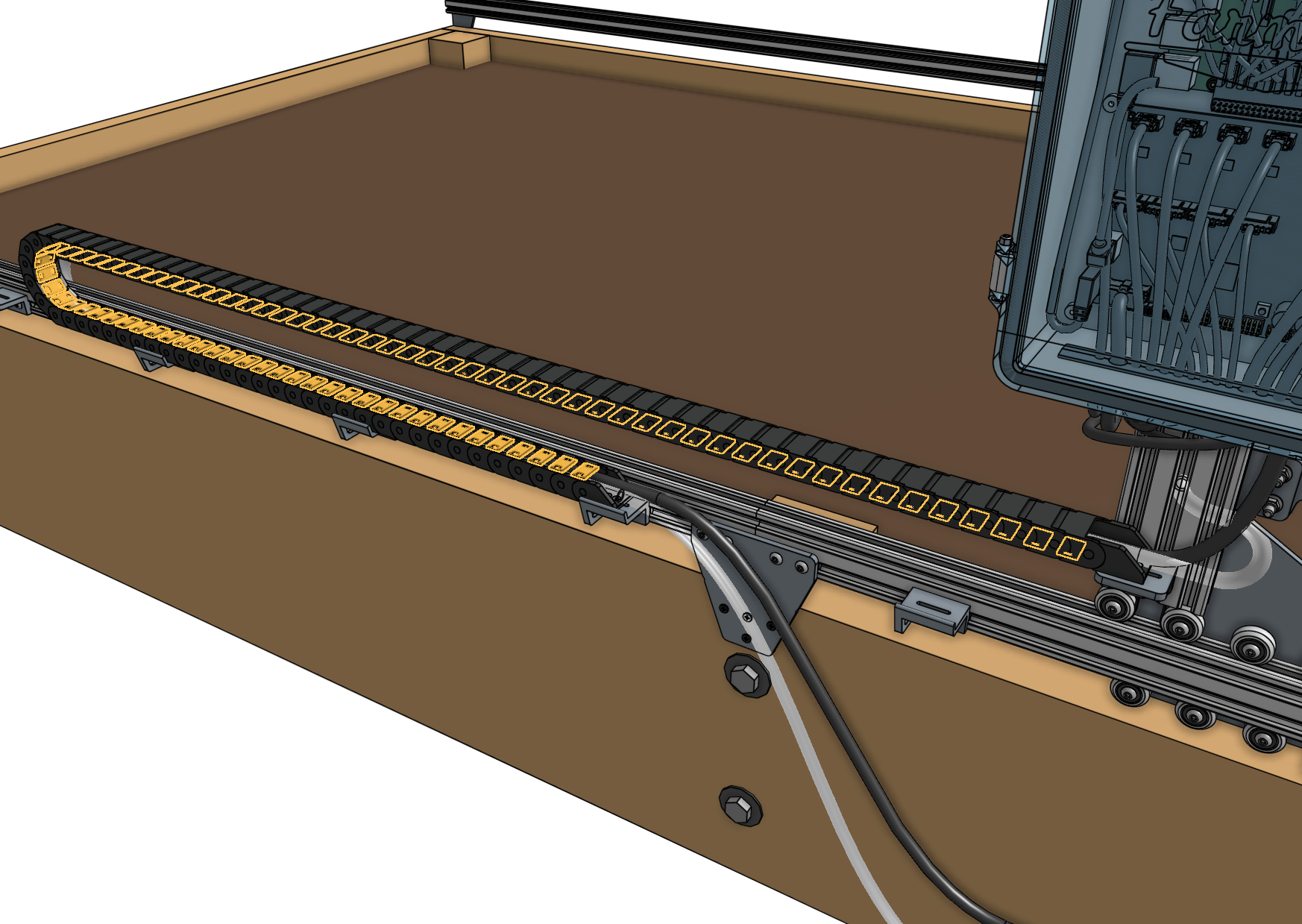
Lay the x-axis water tube and the power supply cable into the open x-axis cable carrier.
The gray connector of the power supply cable should extend beyond the gantry-mounted cable carrier end by about 50cm so that it can plug into the Agriduino.
The water tube should be extended the same distance.
Step 4: Snap in some tabs
Snap in three cable carrier tabs at both ends of the cable carrier, and a few more spread throughout the middle of the cable carrier so the cable and tube stay in place.
You do not want to snap in all of the tabs at this time because that will make it difficult to make adjustments if needed.
Step 5: Mount the cable carrier to the gantry
Attach the x-axis cable carrier to the 30mm horizontal cable carrier mount using two M3 x 16mm flat head screws and M3 locknuts.
Step 6: Mount the cable carrier to the tracks
Attach the other end of the x-axis cable carrier to the 30mm horizontal cable carrier support nearest the middle of the tracks using two M3 x 16mm flat head screws and M3 locknuts.

Step 7: Snap in the remaining tabs
Once everything is situated well, snap-in the remaining cable carrier tabs, ensuring that you maintain organization of the cable and tube.
X-Axis Motors
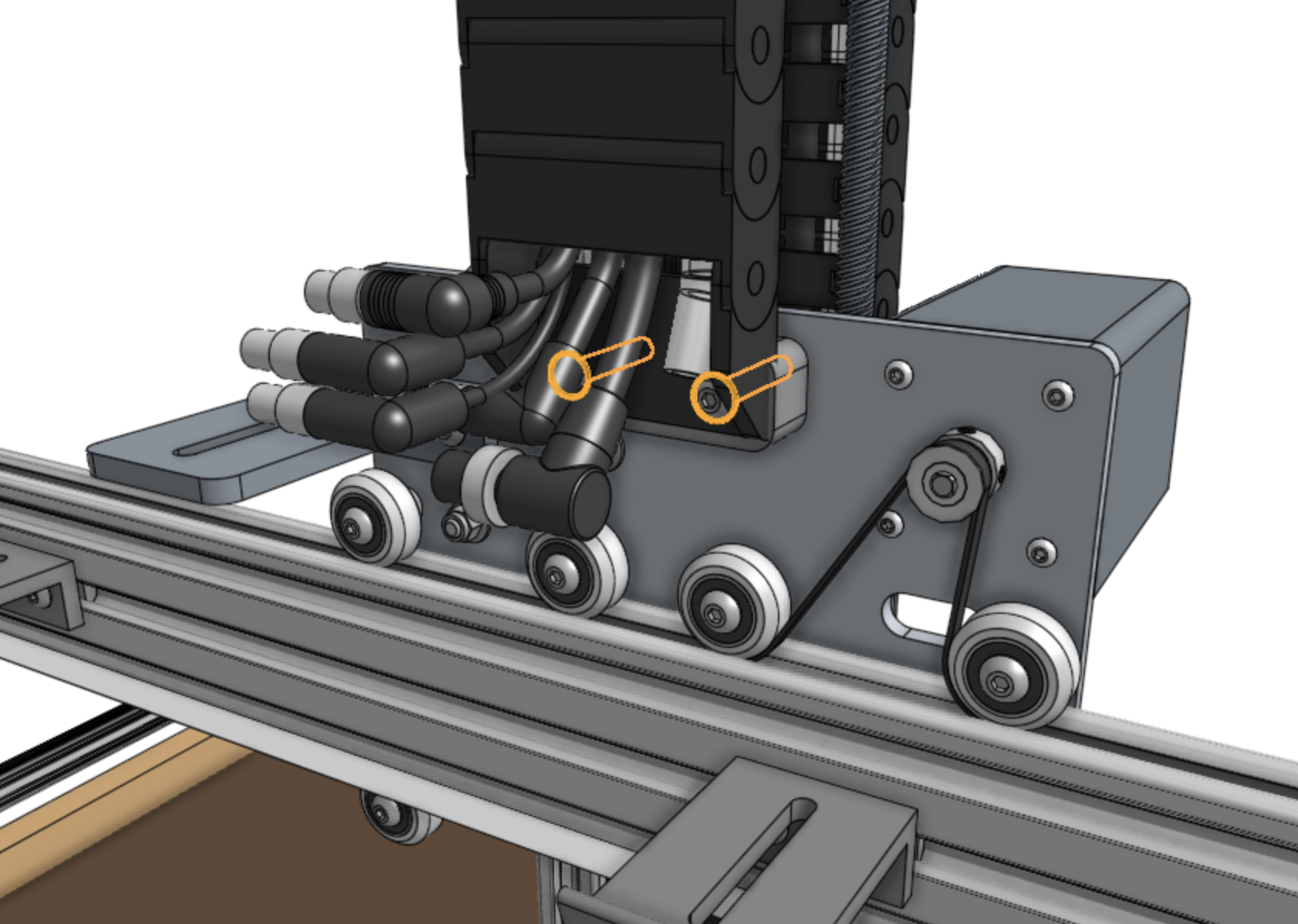
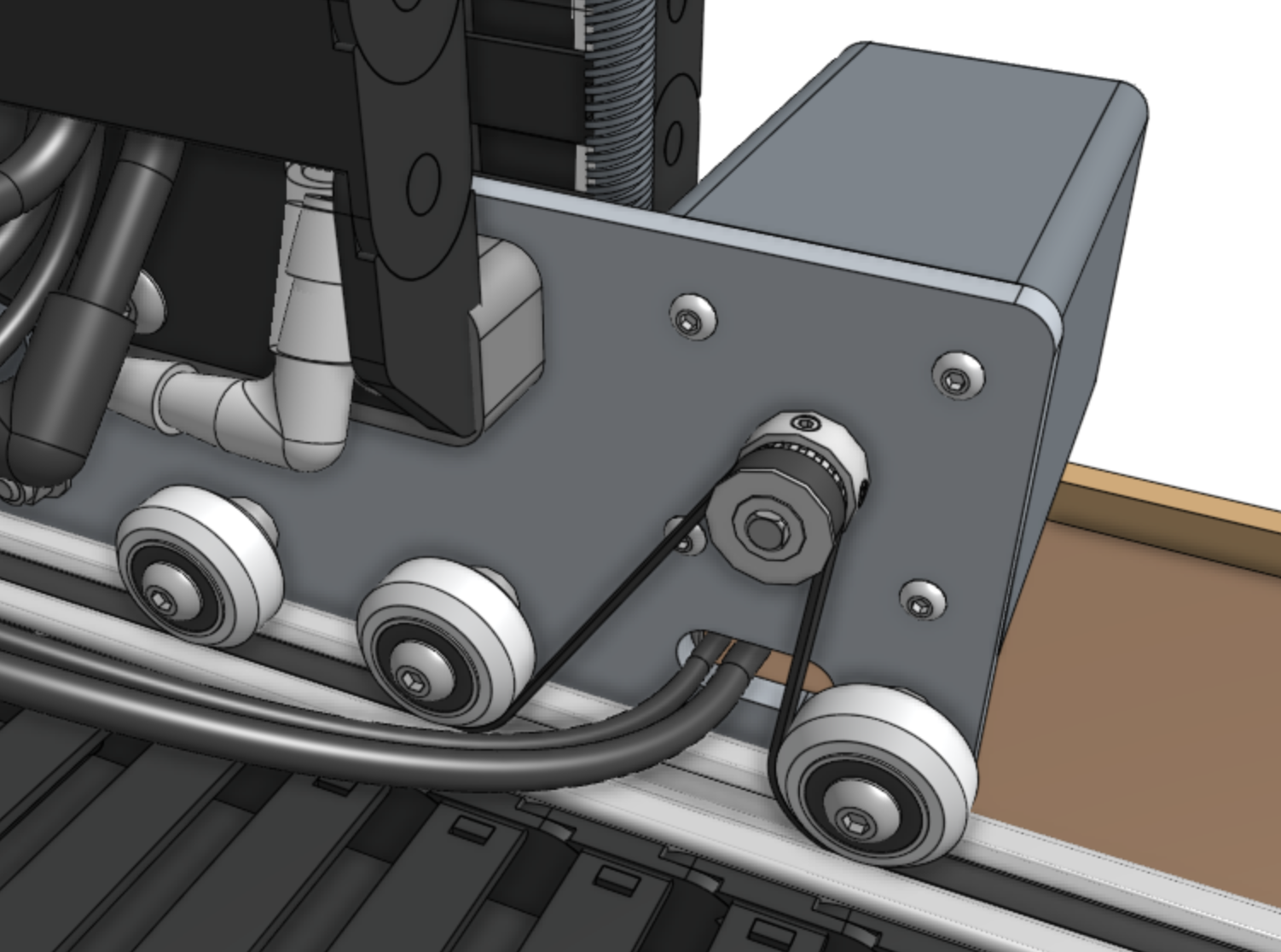
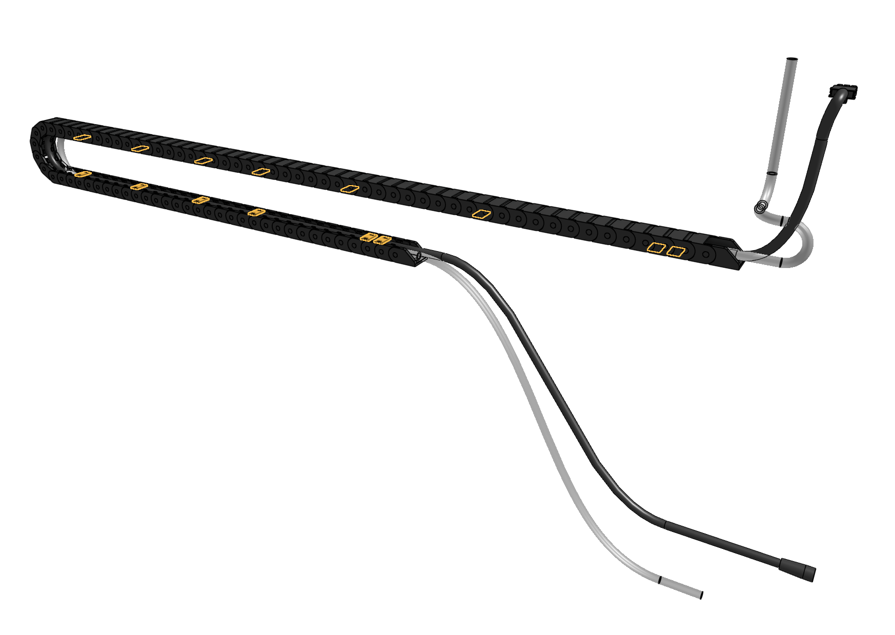
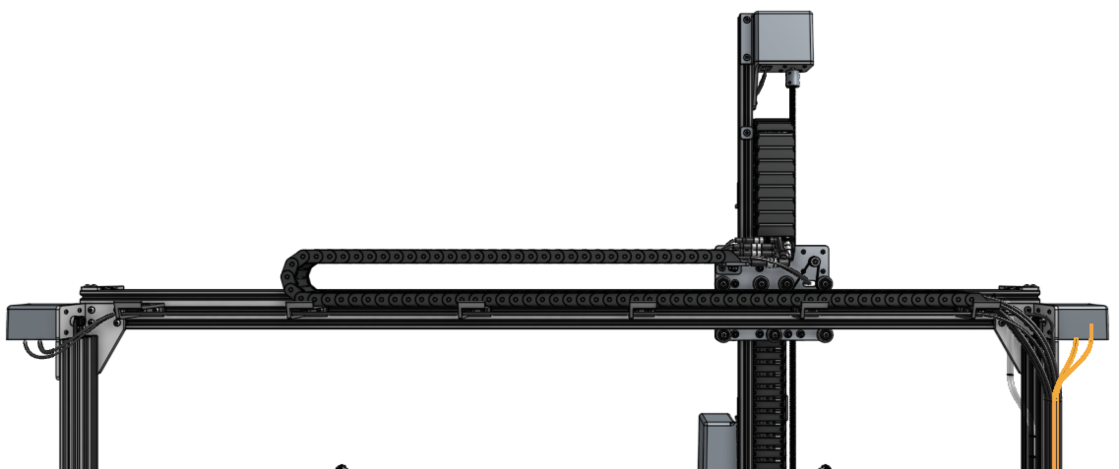
Step 1: Connect the X1 motor and encoder cables
Connect the X1 motor and encoder cables (highlighted orange in the image below) to the X1 motor and encoder on the right side of AgriBot (when looking at the device from the back).
The electronics box will be attached to this side in a later step.
Step 2: Connect the X2 motor and encoder cables
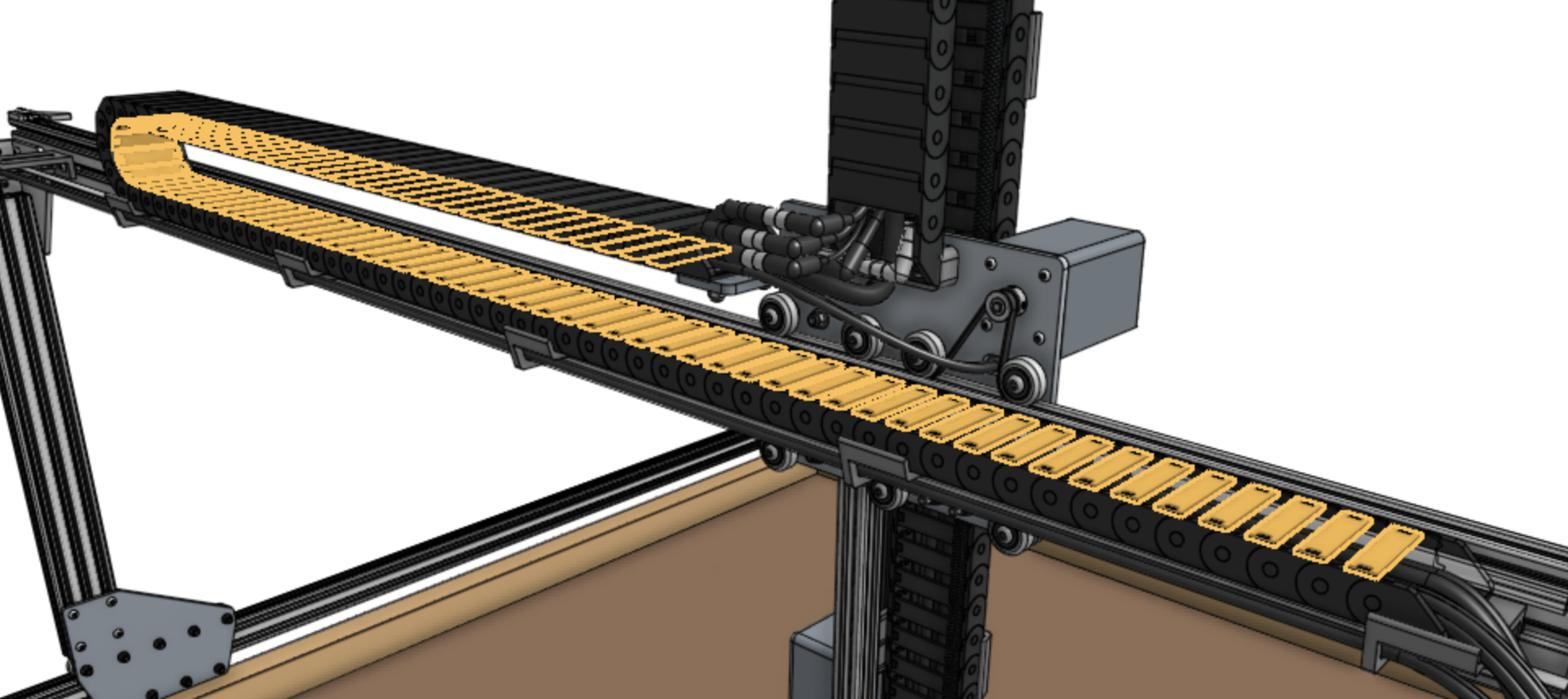
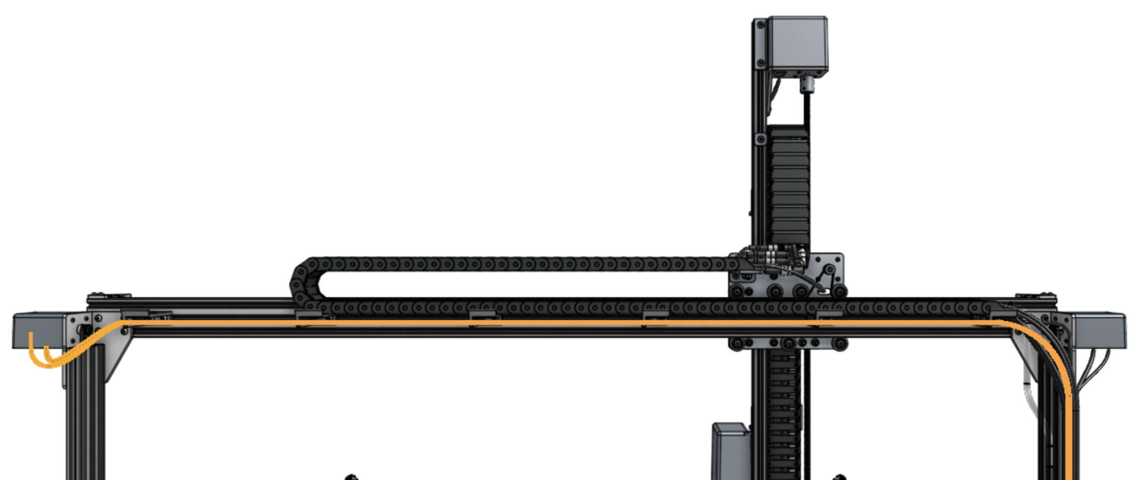
Connect the X2 motor and encoder cables (highlighted orange in the image below) to the X2 motor and encoder on the left side of AgriBot (when looking at the device from the back) by feeding the cables through the slots in all of the horizontal cable carrier supports along the gantry main beam.
Lighting
Install the light strip
Feed the LED strip (highlighted orange in the image below) through the horizontal cable carrier supports on the gantry.
You can secure the end of the strip to the final cable carrier support using a zip tie.
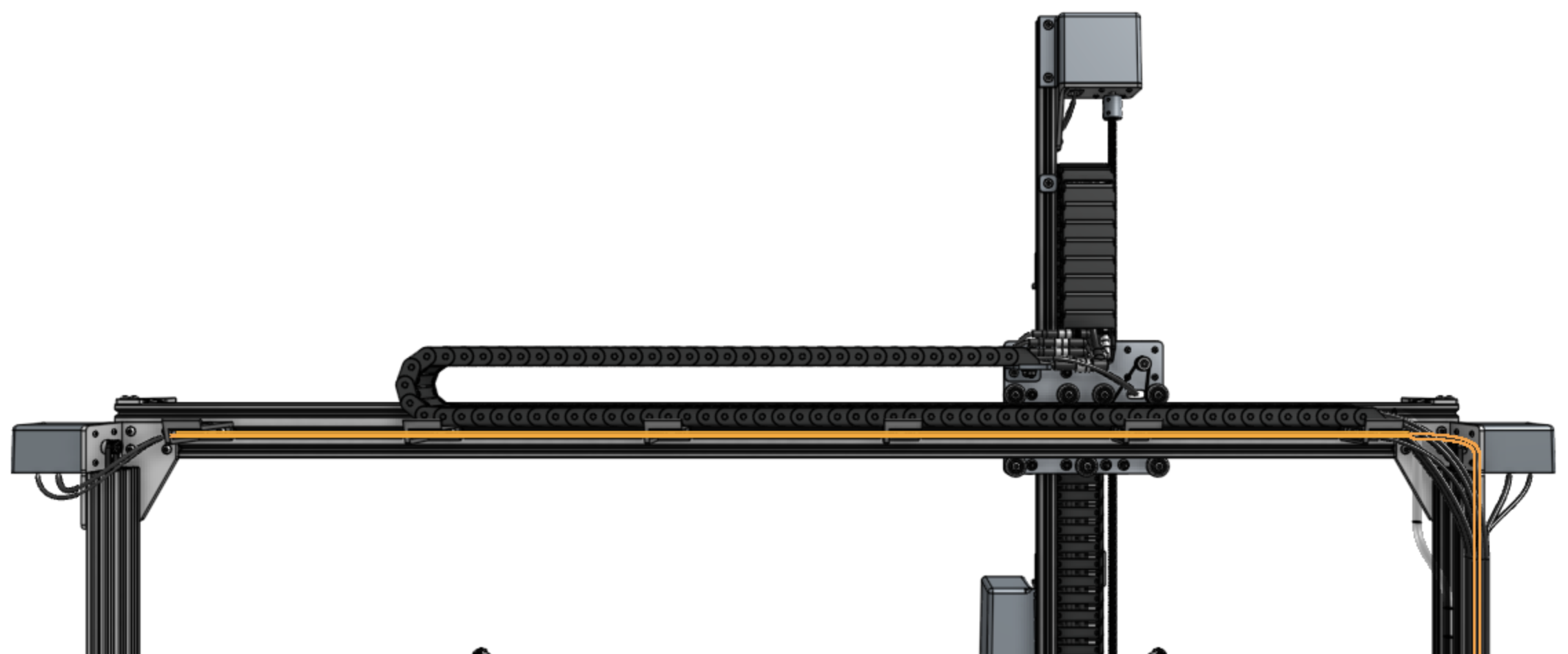
In a few steps from now, you will plug the LED light strip into the Agriduino.