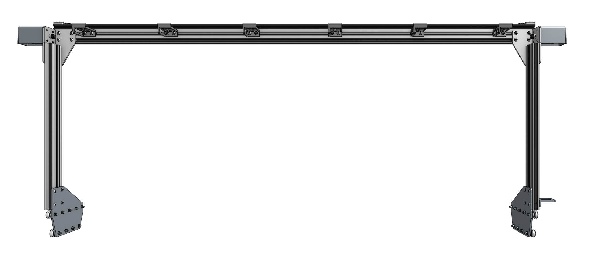
Gantry
Assemble the Gantry Wheel Plates
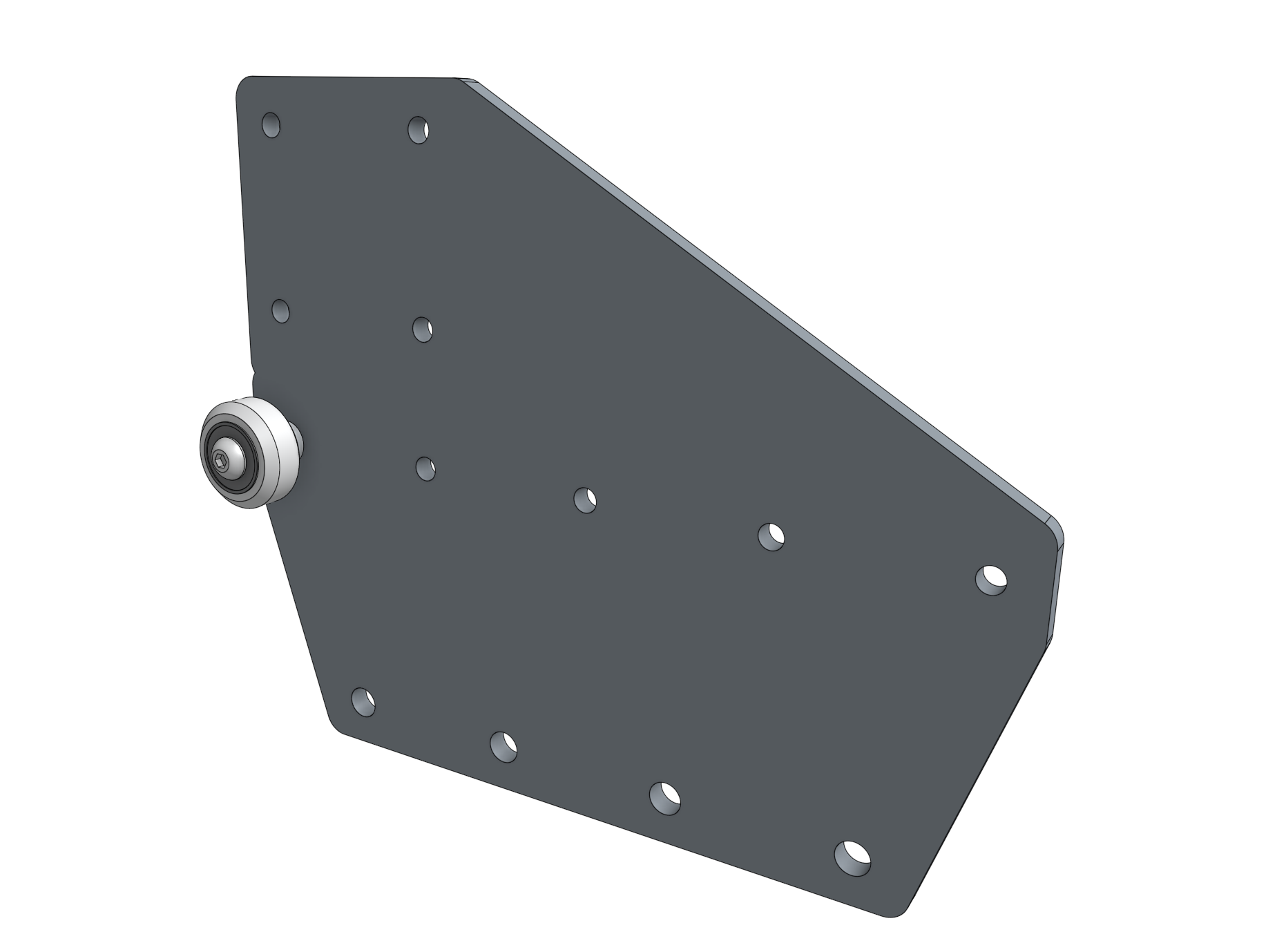
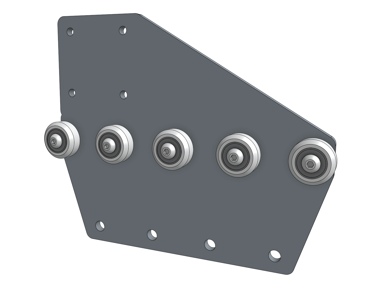
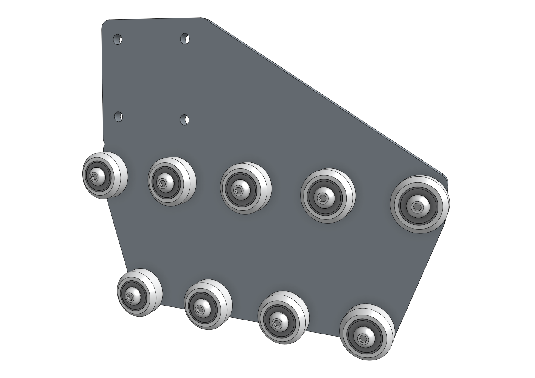
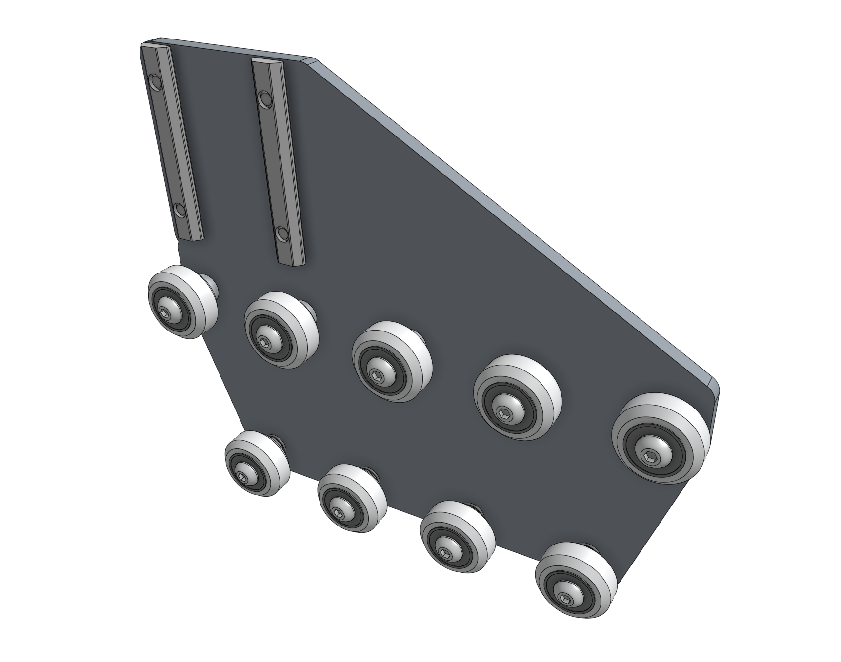
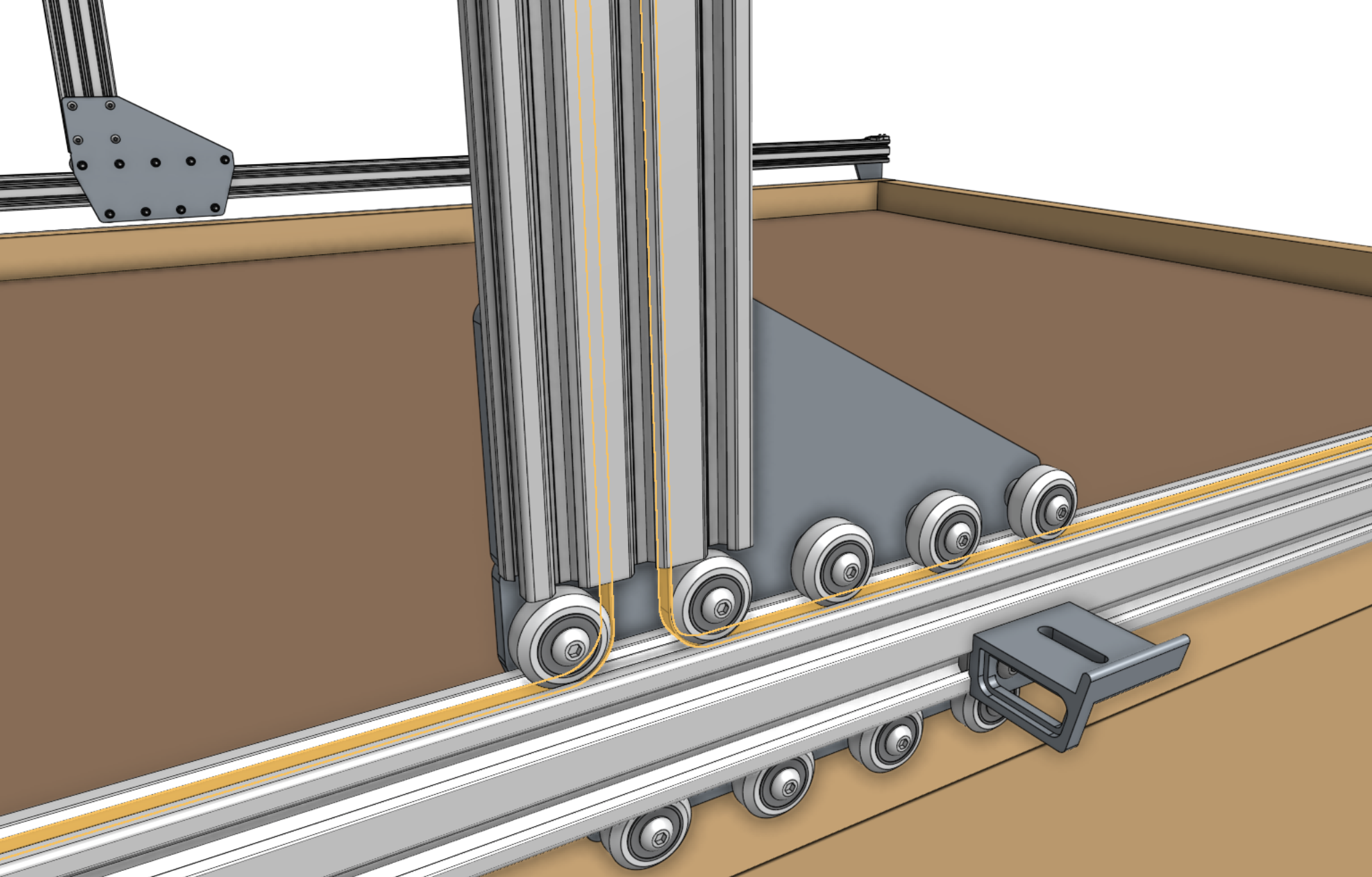
Each gantry wheel plate will have nine wheel assemblies attached to allow sliding along the tracks.
The five wheels that ride on the top of the tracks will be attached to the plates with standard spacers.
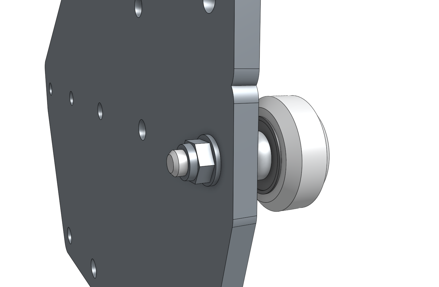
The four wheels that ride underneath the tracks will be attached to the plates with eccentric spacers.
The eccentric spacers will be used to finely adjust the spacing between the top and the bottom wheels such that the gantry will roll smoothly and snuggly along the tracks.
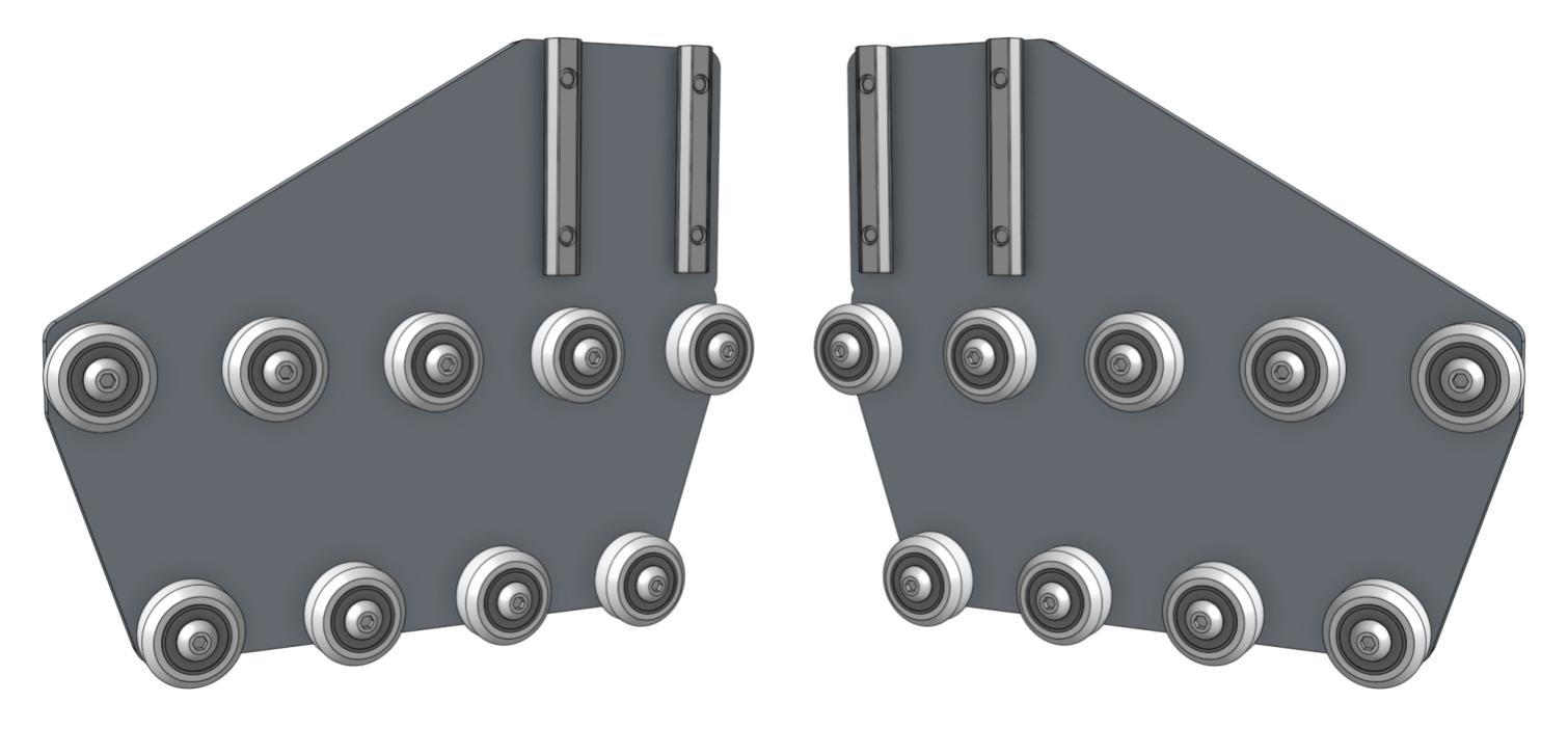
Step 1: Attach the upper V-wheels
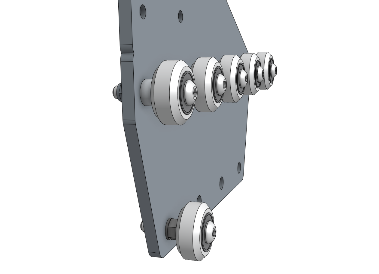
Insert an M5 x 30mm screw through a V-wheel and a standard spacer.
Then insert this into the gantry wheel plate as shown and add an M5 flange locknut on the other side of the plate.
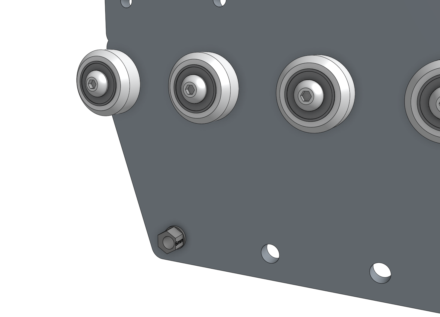
Tighten the wheel assembly using the 3mm hex driver and the 8mm box wrench, then repeat for the remaining four V-wheels with standard spacers.
All five of these wheels should be positioned on the plate in a straight line.
Step 2: Attach the lower V-wheels
Insert an eccentric spacer into the gantry wheel plate.
Then insert an M5 x 30mm screw with a V-wheel through the spacer and secure the assembly with an M5 flange locknut on the other side of the plate.
Repeat for the remaining V-wheels attached with the eccentric spacers.
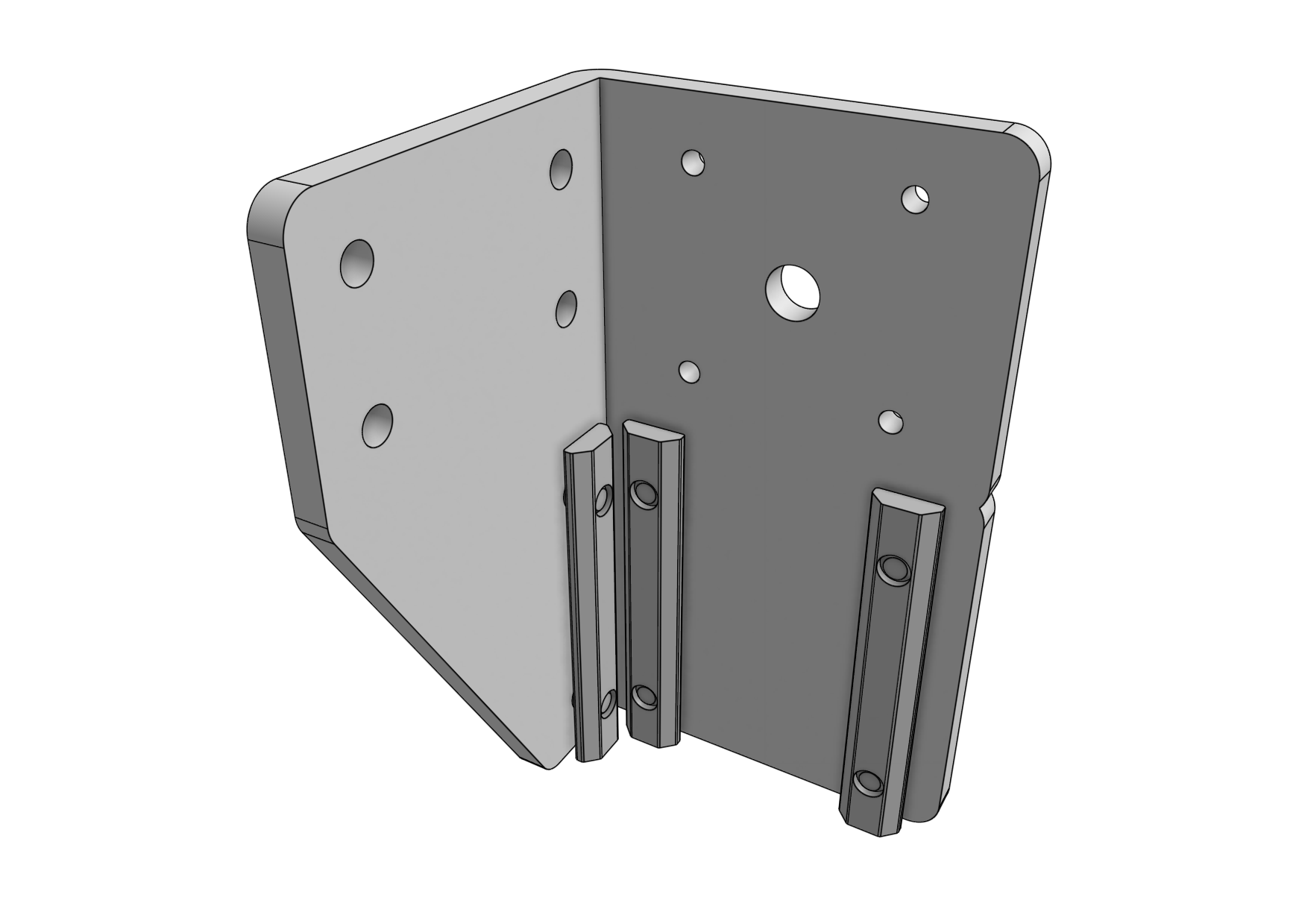
Step 3: Attach the nut bars
Loosely attach two 60mm nut bars to the plate using four M5 x 10mm screws.
The nut bars should reside on the same side of the plate as the V-wheels.
Step 4: Repeat
Repeat the above steps for the second gantry wheel plate assembly.
You should end up with two gantry wheel plate assemblies that are mirror images of each other.

Step 5: Adjust the V-wheel spacing
The eccentric spacers on the lower wheels of each gantry wheel plate assembly are used for making fine adjustments to the spacing between the lower wheels and the upper wheels.
Adjusting this spacing is the key to having your gantry move smoothly and wobble-free across the tracks.
If the spacing is too little, then the gantry will not fit onto the tracks at all or be tough to move.
If the spacing is too great, then the gantry will be wobbly and loose. Adjust the eccentric spacers using the eccentric spacer adjustment reference guide.
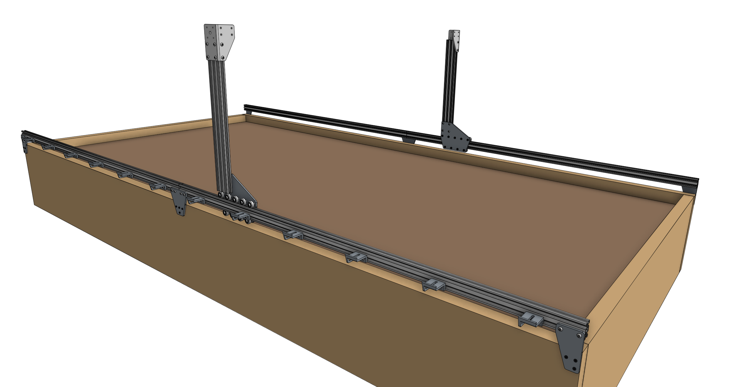
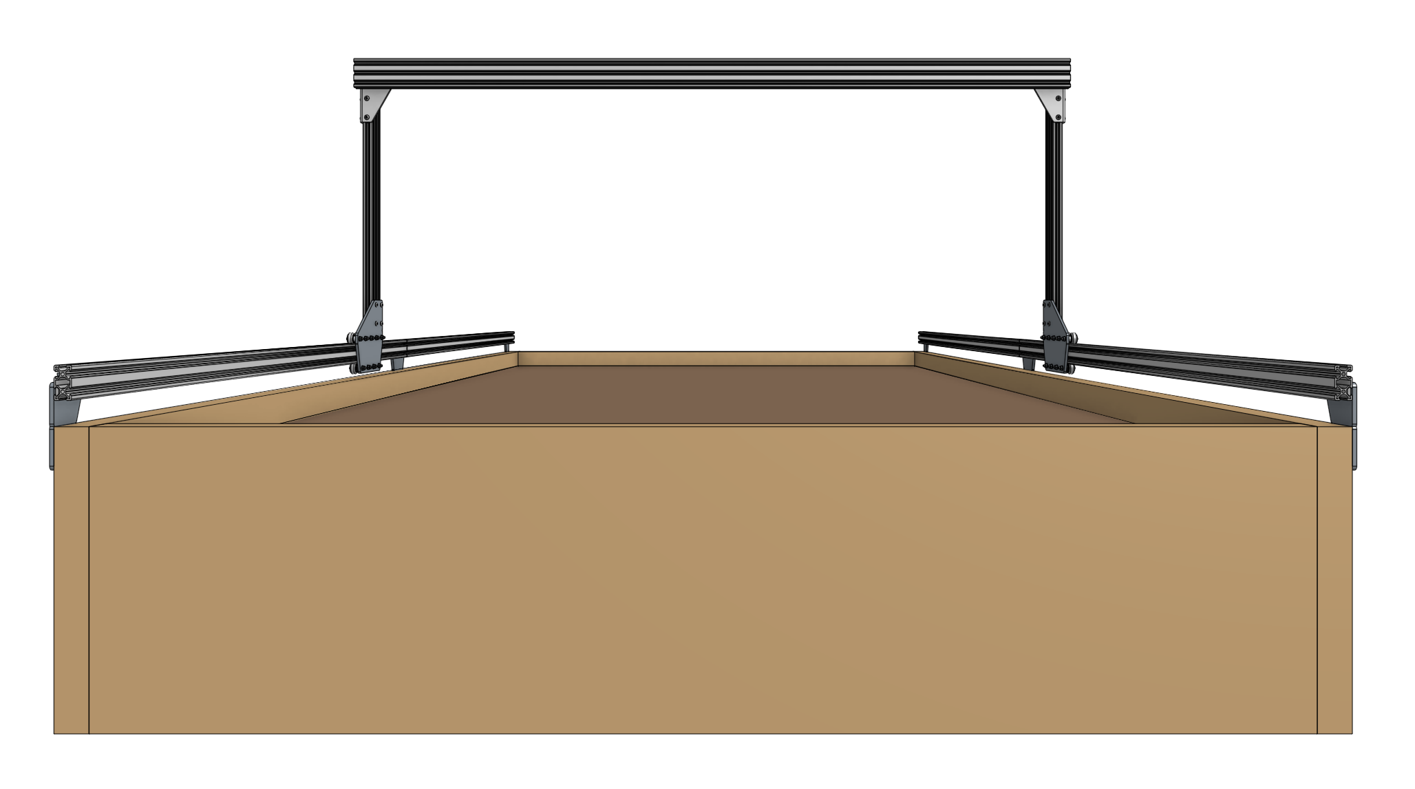
Construct the Gantry Structure
Step 1: Attach the plates to the columns
Slide a gantry column (20mm x 60mm x 500mm extrusion) onto the gantry wheel plate assembly.
The extrusion should reside on the same side of the plate as the V-wheels and the end of the extrusion should be aligned with the notch in the plate.
Tighten the M5 x 10mm screws using the 3mm hex driver.
Repeat for the second gantry wheel plate and aluminum extrusion.

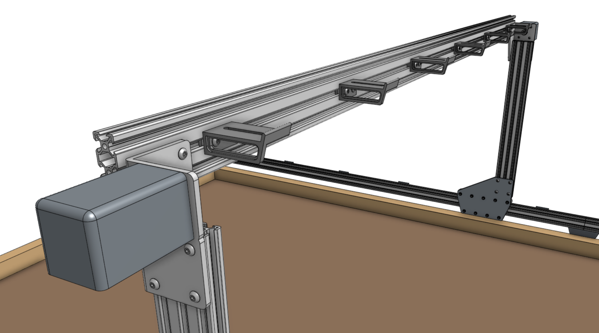
Step 2: Attach the gantry corner brackets
Lightly attach three 60mm nut bars to each gantry corner bracket using M5 x 10mm screws.
Then slide the corner brackets onto the gantry column/plate assemblies.
The top of the extrusions should line up with the notches in the corner brackets.


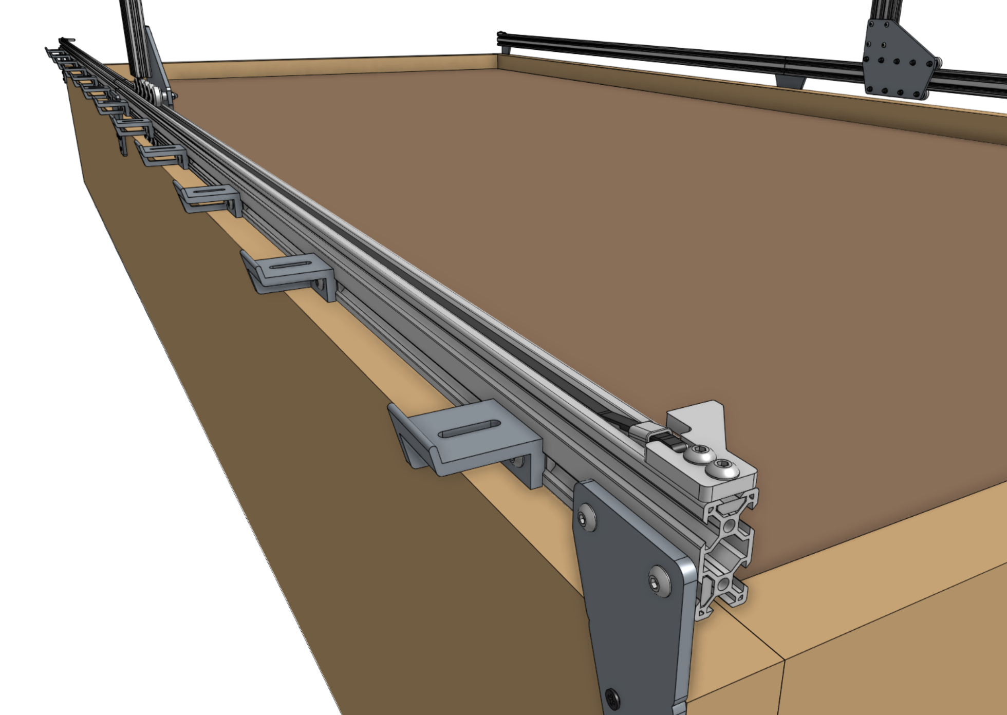
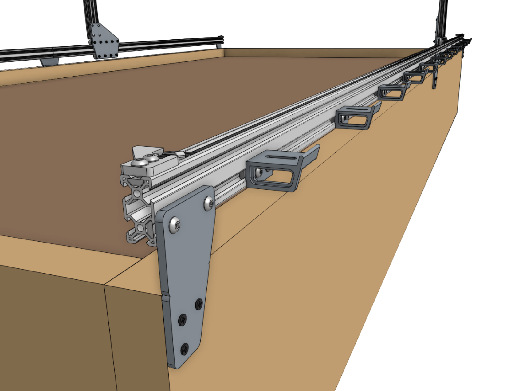
Step 3: Slide onto the tracks
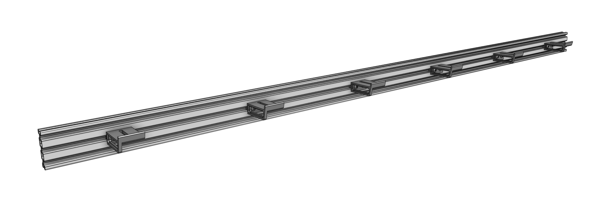
Slide the gantry columns onto the tracks.
The direction that the wheel plates extend from the column is towards the front of AgriBot.
Ensure that the cable carrier supports (mounted to the tracks) are on the left side of the AgriBot.
Step 4: Assemble the main beam
Place both gantry main beams on a flat surface such as a table or patio.
Using two 140mm nut bars and eight M5 x 10mm screws, attach the gantry joining bracket to the lower two slots of both extrusions.
The notch in the middle of the bracket should be aligned with the joint between the two extrusions.
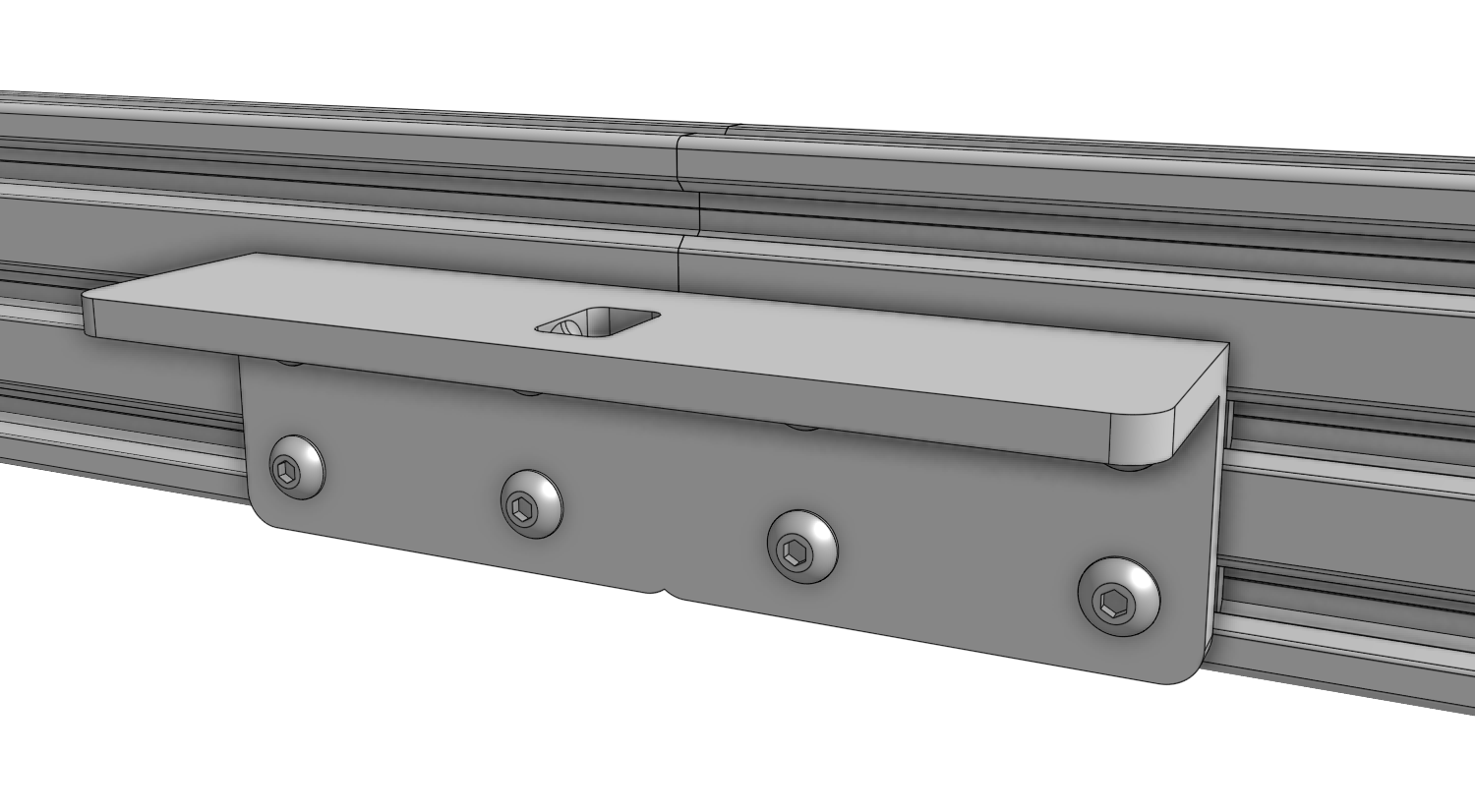
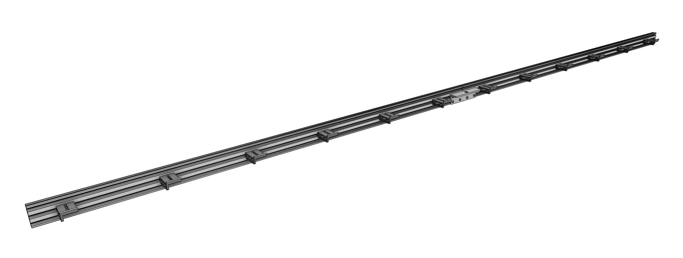
Step 5: Attach the cable carrier supports
Using M5 x 10mm screws and 40mm nut bars, attach six 60mm horizontal cable carrier supports to the middle slot of the gantry main beam extrusion.
For normal kits, there is only one main beam extrusion, so only six supports will be used.
For XL kits, there are two main beam extrusions, so 12 supports will be used, and they should be positioned on the same side of the extrusions as the gantry joining bracket.
Step 6: Attach the main beam
Lift up the gantry main beam and position it onto the front of the gantry corner brackets.
The cable carrier supports should be on the same side of the main beam as the gantry corner brackets.
Secure the main beam in place using four 60mm nut bars and M5 x 10mm screws.
The nut bars should be positioned in the lower two extrusion slots of the main beam such that the top face of the main beam is 20mm above the top edges of the gantry corner brackets.

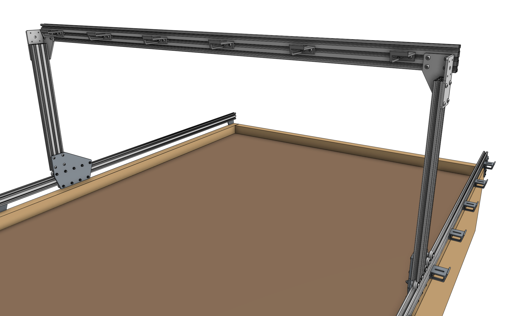
Ensure that the gantry columns are vertical and form a 90 degree angle with the main beam.
Then tighten the M5 x 10mm screws. Depending on the spacing of your tracks, the gantry main beam may extend beyond the corner brackets. This is ok.
Step 7: Attach the x-axis cable carrier mount
Use two M5 x 10mm screws and tee nuts to attach the aluminum 35mm cable carrier mount to the bottom of the left gantry column.

Attach the Drivetrain
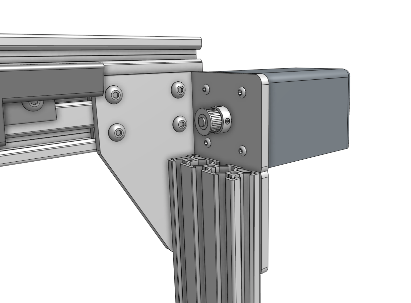
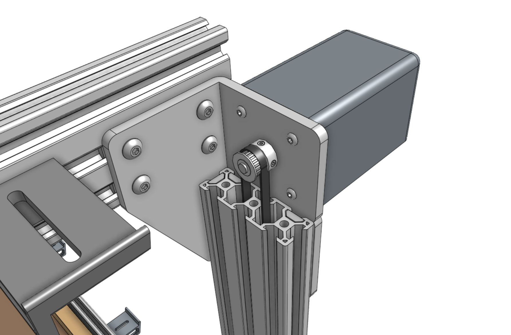
Step 1: Attach the gantry motors
Slide a motor into a horizontal motor housing, ensuring that the shaft of the motor is coming out of the housing and that the motor and encoder connectors are facing down through the open bottom of the housing.
Then attach the motor and housing to a gantry corner bracket with four M3 x 12mm screws.
Repeat for the second motor on the other gantry corner bracket.
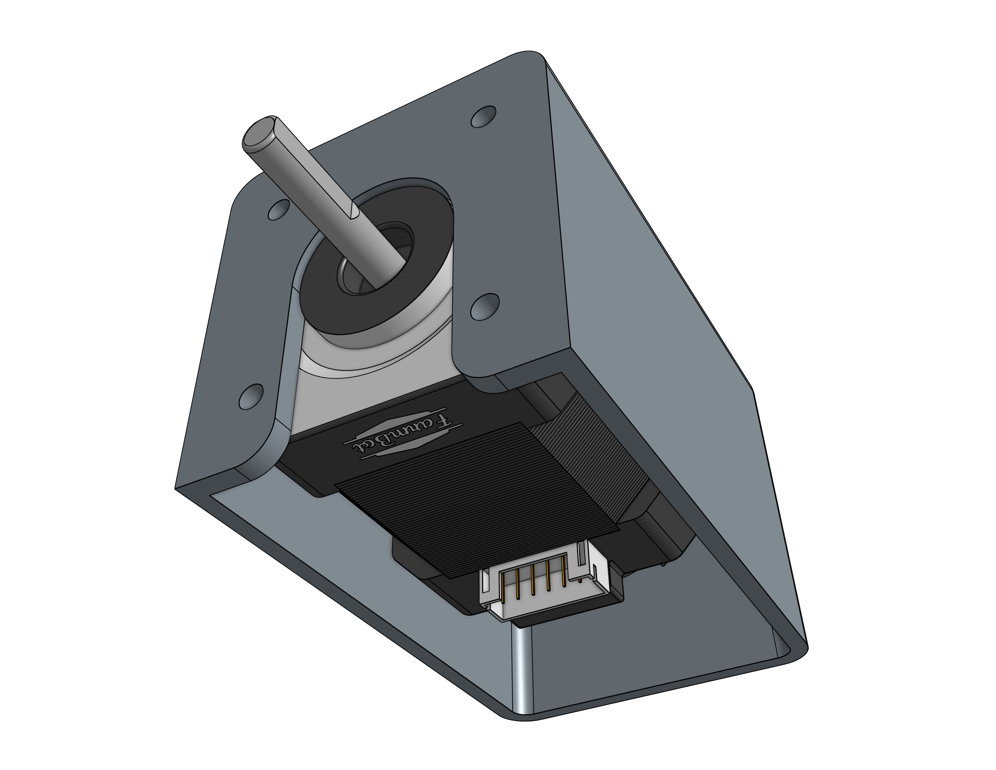
Slide pulleys onto the motor shafts and tighten the two set screws (pre-inserted) with the 2mm hex driver.
Make sure that the setscrews contact the flat areas on the motor shafts.
Step 2: Feed the belts
Drop the ends of one of the x-axis GT2 timing belts down the two large openings of a gantry column, ensuring that the belt teeth engage the pulley.
Grab the ends of the belt at the bottom of the gantry column and feed them under the V-wheels of the gantry wheel plate, then along the top of the track extrusions to the ends of the tracks.
The flat side of the belt should be in contact with the V-wheels.
Step 3: Secure the belts
Secure one end of the belt to the front end of the tracks by using a belt clip, belt sleeve, 20mm nut bar, and two M5 x 10mm screws.
The belt must be wrapped through the clip as outlined in the belt installation guide. Repeat for the other end of the belt on the other end of the tracks.
Then repeat for the second x-axis belt on the other side of the AgriBot.
Trim or coil any extra belt, if desired.
Step 4: Equalize the gantry
To equalize the gantry, first ensure that the x-axis motors are unpowered.
For first time installation this will always be the case because we haven’t yet added the wires or electronics!
Then gently push or pull on the gantry from the middle of the gantry main beam such that it moves slowly along the tracks about 30cm.
This process will remove any torque on the gantry, and ensure it is not crooked.
If you push or pull the gantry from one of the gantry columns, or anywhere that is not the middle of the main beam, then you will torque the gantry and make it crooked. Don’t do that.
If you were equalizing the gantry as part of routine maintenance, remember to after equalization.